FreeCAD-Ship s60 tutorial: Difference between revisions
(Outline draw chapter added) |
(Transversal areas curve chapter added) |
||
| Line 119: | Line 119: | ||
[[Image:FreeCAD-Ship-S60Outline3DSections.png|center|Resultant sections.]] |
[[Image:FreeCAD-Ship-S60Outline3DSections.png|center|Resultant sections.]] |
||
<center><span style="font-variant:small-caps">Resultant sections.</span></center> |
<center><span style="font-variant:small-caps">Resultant sections.</span></center> |
||
== Transversal areas curve == |
|||
One typical ship design hydrodynamic parameter is the transversal areas curve, that retrieves some indicators about the behaviour of the hull (towing resistance, seakeeping, ...). FreeCAD-Ship provides a simple tool in order to perform transversal areas curve. |
|||
[[Image:FreeCAD-Ship-AreaCurveIco.png|center|Transversal areas curve tool icon.]] |
|||
<center><span style="font-variant:small-caps">Transversal areas curve tool icon.</span></center> |
|||
When tool is executed a task dialog is shown, and free surface prewied is created at 3D view (Free surface preview will be removed when tool finished, so don't take care about them). Into task dialog input and output data is present. |
|||
=== Input data === |
|||
Draft and trim (Hull ''y edge'' rotation angle, positive if stern draft may increase) must be provided. Several areas curves may be performed, depending on ship load situations, but two typical plot should be performed: |
|||
* Design transversal areas curve: Without triming angle and using design draft, 1.0 m in this case. |
|||
* Maximum draft transversal areas curve: Without trimin angle, and maximum draft allowed, 2.0 m in this case. |
|||
=== Output data === |
|||
Some relevant data is shown at real time: |
|||
* '''L''': Lenght between perpendiculars, value set at ship instance creation. |
|||
* '''B''': Beam selected at ship creation. |
|||
* '''T''': Actual aim frame draft. |
|||
* '''Trim''': Trim angle. |
|||
* '''T<sub>AP</sub>''': After perpendicular draft. |
|||
* '''T<sub>FP</sub>''': Forward perpendicular draft. |
|||
* '''Displacement''': Ship displacement (salt water consideered, divide by 1.025 in order to know displaced volume). |
|||
* '''XCB''': Bouyance center point X coordinate (relative to amin frame). |
|||
When '''Accept''' button is pressed a plot is performed. |
|||
[[Image:FreeCAD-Ship-s60Areas.png|center|Design draft transversal areas curve. ]] |
|||
<center><span style="font-variant:small-caps">Design draft transversal areas curve. </span></center> |
|||
FreeCAD ship use [http://www.pyxplot.org.uk/ pyxplot] in order to generate plot as '''*.eps''' image, and [http://www.ghostscript.com/ ghostscript] in order to convert it to '''*.png''' image. If you open FreeCAD from terminal you can see where data has been saved, near to data file several auxiliar files has been created too: |
|||
* '''areas.dat''': Contains transversal areas data. |
|||
* '''areas.pyxplot''': pyxplot layout in order to plot '''areas.dat''' sheet. |
|||
* '''areas.eps''': EPS image version (best chice in order to edit it). |
|||
* '''areas.png''': Final image PNG version. |
|||
When new transversal areas curve is performed files will be overwritten, so copy it at other place if you want to preserve it. |
|||
[[Category:Tutorials]] |
[[Category:Tutorials]] |
||
Revision as of 12:21, 10 February 2012
In this tutorial we will work with Serie 60 ship, from the Iowa University. The tutorial is aimed to show how to work with a symmetric monohull ship.
You can learn more about FreeCAD-Ship here
Loading geometry
Introduction
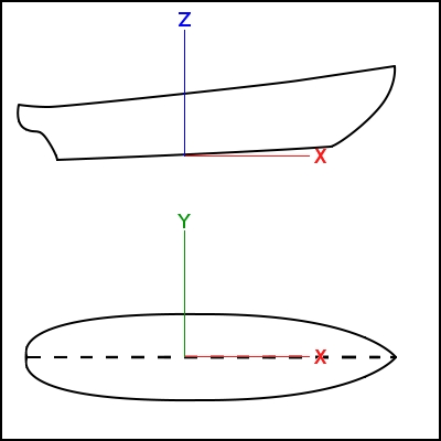
FreeCAD-Ship works over Ship entities, that must be created on top of provided geometry. Geommetry can be a set of surfaces or solids, but following criteria must be taken into account:
- Only symmetric ships are supported yet, so only half starboard geometry must be provided.
- Starboard geometry must be included at negatives y domain.
- Origin (0,0,0) point is the Amin frame and base line intersection.
Loading Serie 60 geometry
In order to help new users FreeCAD-Ship includes an example geometries loader.

Executing the tool (Ship design/Load an example ship geometry) a task dialog will shown. Select Serie 60 from Iowa University and press Accept. Tool loads new document with s60_IowaUniversity geometry.
Create ship instance
In order to create a Ship instance select s60 geometry and execute the ship creation tool (Ship design/Create a new ship).

Creating ship task dialog and some annotations at 3D view will shown. The annotations will removed when you close Ship creation tool, so don't take care about this.
Ship creation has two blocks, ship data and discretization data.
Ship data
Main dimensions must be introduced here:
- Length: Length between perpendiculars, 25.5 m for this ship.
- Beam: Total ship beam, 3.389 m for this ship.
- Draft: Design draft, 1.0 m for this ship.

Ussually Length between perpendiculars depends on design draft, so if you don't know what is the length of your ship you can set draft, and fit length in order to get bow and draft intersection.
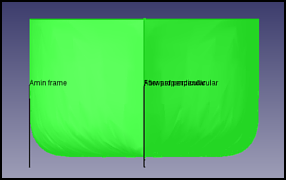
Same process is valid for Beam fit. Note that is total beam, so symmetric hiden ship part must be taken into account.
Discretization data
FreeCAD-Ship use for basic calculation process a transversal cuts discretization version of the geometry, so discretization data must be provided. Depending on geometry discretization process can take some time, but future calculations are not heavily affected. If you don't need great results and don't want waste a lot of time, you can get default values, but you can consideer increase the values in order to improve results.
We will select 100x20.
When you press Accept button the program start discretization process, that may take less than one minute (More complex geometries can take hours, take care about this). The program can seems hanged, but if you executed FreeCAD from terminal you can follow progress, and cancel pressing Ctrl+C (Ship will not created).
When discretization ends you have your new Ship instance called Ship at Tags & Attributes dialog. We don't need geometry anymore, so you can hide it.

Until now Ship must be selected before execute any FreeCAD-Ship tool.
Outline draw
FreeCAD-Ship provides a tool in order to make easy exporting ship outline draw.

Outline draw is a set of cuts that allows to meet the hull geometry with a standarized plot. Outline drawing needs the cuts set.
Transversal cuts
Ussualy 21 transversal equi-distance sections between perpendiculars must be performed. in order to do it FreeCAD provides an automatic tool in order to do it, simply select Transversal type of sections, go to Auto create box and set 21 sections, then press Create sections.
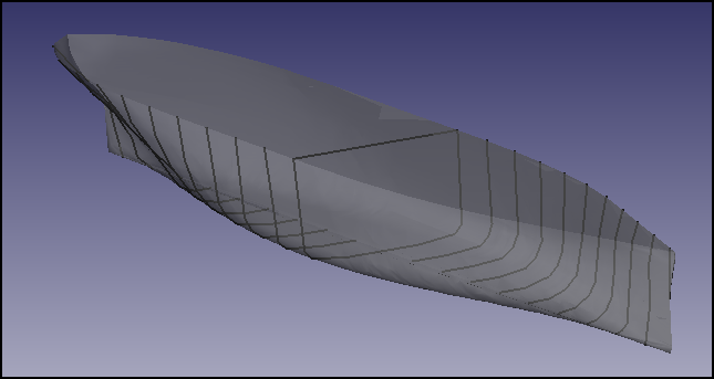
Sections table is filled, and sections preview called OutlineDraw shown. Ussually mor sections was added at bow and stern, where more complex curvatures are registered, in order to do it go to the end of the table, and do double click at empty item in order to edit it, pressing intro to confirm. Add following sections:
- X22 = -12.1125 m
- X23 = 12.1125 m
Longitudinal cuts
Two longitudinal cuts must be added, so select Longitudinal type of sections, go to Auto create box and set 2 sections, then press Create sections. Sections table is filled, and sections preview updated.
Water lines
6 Water lines beteewn base line and design draft must be added, so select Water lines type of sections, go to Auto create box and set 5 (Z = 0 m will not considereed, add it manually if you needs it) sections, then press Create sections. Sections table is filled, and sections preview updated.
Several additional water lines must be added:
- Z6 = 1.2 m
- Z7 = 1.4 m
- Z8 = 1.6 m
- Z9 = 1.8 m
- Z10 = 2.0 m
Perform plot
Select 1:100 scale and press Accept. Plot is performed, you can learn more about plotting and how to edit it here.

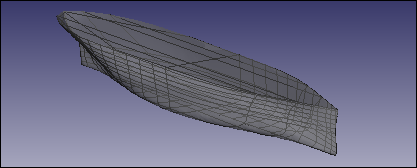
3D sections are preserved to in order you can work with them (i.e.- Multifaces ships may have undesired edges at plot).
Transversal areas curve
One typical ship design hydrodynamic parameter is the transversal areas curve, that retrieves some indicators about the behaviour of the hull (towing resistance, seakeeping, ...). FreeCAD-Ship provides a simple tool in order to perform transversal areas curve.

When tool is executed a task dialog is shown, and free surface prewied is created at 3D view (Free surface preview will be removed when tool finished, so don't take care about them). Into task dialog input and output data is present.
Input data
Draft and trim (Hull y edge rotation angle, positive if stern draft may increase) must be provided. Several areas curves may be performed, depending on ship load situations, but two typical plot should be performed:
- Design transversal areas curve: Without triming angle and using design draft, 1.0 m in this case.
- Maximum draft transversal areas curve: Without trimin angle, and maximum draft allowed, 2.0 m in this case.
Output data
Some relevant data is shown at real time:
- L: Lenght between perpendiculars, value set at ship instance creation.
- B: Beam selected at ship creation.
- T: Actual aim frame draft.
- Trim: Trim angle.
- TAP: After perpendicular draft.
- TFP: Forward perpendicular draft.
- Displacement: Ship displacement (salt water consideered, divide by 1.025 in order to know displaced volume).
- XCB: Bouyance center point X coordinate (relative to amin frame).
When Accept button is pressed a plot is performed.
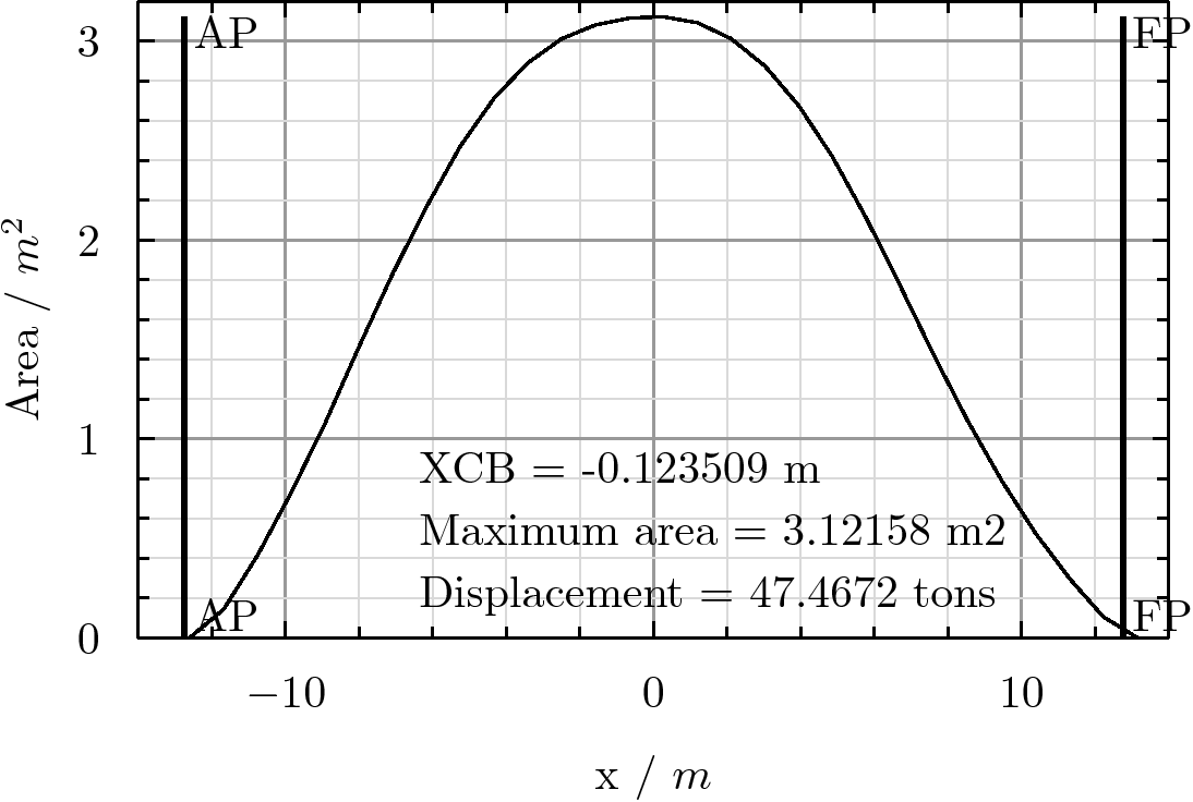
FreeCAD ship use pyxplot in order to generate plot as *.eps image, and ghostscript in order to convert it to *.png image. If you open FreeCAD from terminal you can see where data has been saved, near to data file several auxiliar files has been created too:
- areas.dat: Contains transversal areas data.
- areas.pyxplot: pyxplot layout in order to plot areas.dat sheet.
- areas.eps: EPS image version (best chice in order to edit it).
- areas.png: Final image PNG version.
When new transversal areas curve is performed files will be overwritten, so copy it at other place if you want to preserve it.