FEM Shear of a Composite Block/fr: Difference between revisions
(Created page with "Note2 : si vous avez des difficultés à choisir "CompoundFilter:Solid2" il peut être parce que vous avez oublié de mettre le mode BooleanFragments à CompSolid.") |
(Created page with "Le matériel(La matière) est assigné Prendre au filet des Régions via un objet SolidMaterial. Dans ces travaux dirigés(didacticiel) nous assignons deux matériels(matière...") |
||
| Line 45: | Line 45: | ||
Le matériel(La matière) est assigné Prendre au filet des Régions via un objet SolidMaterial. Dans ces travaux dirigés(didacticiel) nous assignons deux matériels(matières); un pour la Matrice et un pour le Cœur. |
|||
Material is assigned to Mesh Regions via a SolidMaterial object. In this tutorial we assign two materials; one for the Matrix and one for the Core. |
|||
Revision as of 15:22, 28 April 2018
| Thème |
|---|
| Analyse d'éléments finis |
| Niveau |
| Débutant/intermédiaire |
| Temps d'exécution estimé |
| 30 minutes |
| Auteurs |
| HarryvL |
| Version de FreeCAD |
| 0.17.12960 ou ultérieur |
| Fichiers exemples |
| Voir aussi |
| None |
L'introduction
Dans ces travaux dirigés nous analysons la déformation se tondant d'un bloc composite consistant d'un coeur raide incorporé dans une matrice douce. Il démontre l'utilisation de BooleanFragments et CompoundFilter pour créer des aliments solides pour le bloc et la matrice de deux cubes concentriques. Ce workflow assure que MeshRegions séparé, des Matériels et des Conditions de Frontière peuvent être définis pour le bloc et la matrice environnante. Pour choisir des régions internes nous nous faisons de la macro par Markus Hovorka (https://github.com/drhooves/SelectionTools). Les résultats de CalculiX montrent clairement l'effet du coeur raide sur la réponse du bloc composite.
Géométrie
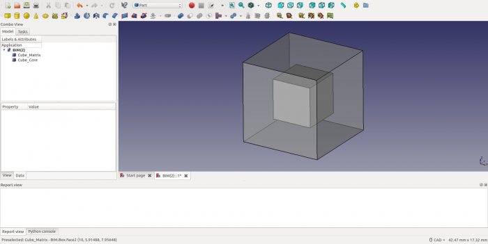
D'abord nous créons deux cubes concentriques, une taille 10mm et l'autre taille 5mm. Ceci est fait dans l'établi "la Partie". Par défaut le cube est placé(situé) de l'origine [0, 0, 0], donc le cube plus petit doit être réduit et changé en changeant les fixations à l'étiquette(onglet) de Données du panneau(jury) de propriété. Pour faire le cœur visible, la Transparence du bloc extérieur est mise à 50 à l'étiquette(onglet) de Vue du panneau(jury) de propriété. On montre le résultat ci-dessous.
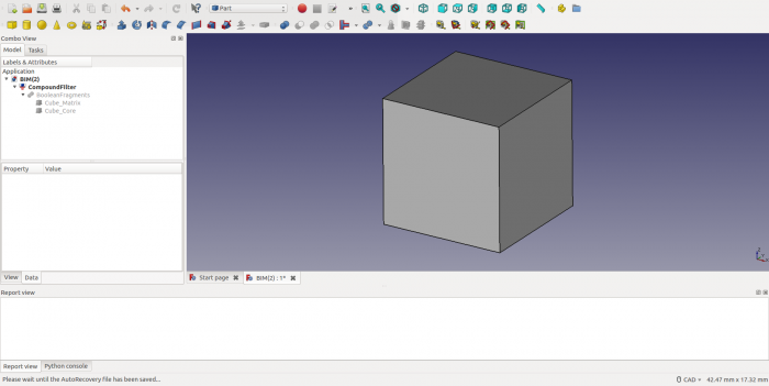
Le point culminant suivant les deux blocs dans l'arbre et crée un objet de BooleanFragments (la Partie > la Rupture > des Fragments Booléens). Dans "la Fenêtre de Propriété - la Languette de Données" change le Mode à CompSolid. Mettez maintenant en évidence le BooleanFragments dans l'arbre d'Objet et créez un CompoundFilter (la Partie > le Composé > le Filtre Composé).
Maille et Régions de Maille
De l'établi FEM nous créons un conteneur d'Analyse. Ceci contiendra toutes les définitions exigées pour l'analyse CalculiX et ses résultats. Notez que ce conteneur d'Analyse doit être activé (pour faire un clic droit et la sélection "Active l'analyse") en rechargeant le fichier(dossier) ou après la commutation en arrière d'autres analyses. Pour commencer le processus de maillage, mettez en évidence(surlignez) le CompoundFilter dans l'Arbre d'Objet et activez le dialogue concordant "la Maille > FEM la maille de la forme par Gmsh". Laissez(quittez) le dialogue en cliquetant OK.
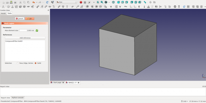
Un objet de Maille est maintenant créé dans l'Arbre d'Objet. Mettez en évidence cet objet et créez un objet de Région de Maille via "la Maille > la région de maille de FEM". Ouvrez la boîte de dialogue pour cette Région de Maille en double cliquant et cochez le bouton de radio pour Solide. Le clic suivant le "Ajoute la Référence" le bouton et choisit l'objet de CompoundFilter dans la Fenêtre Graphique. Ceci devrait ajouter une référence à "CompoundFilter:Solid1" dans la liste d'objet de la Région de Maille. Spécifiez finalement la taille d'élément maximale pour cette région (5mm dans l'analyse actuelle). Laissez le dialogue en cliquant sur OK.
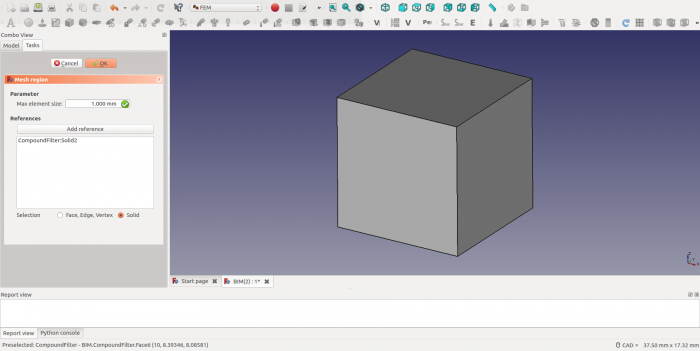
Créez ensuite un nouvel objet de Maille comme ci-dessus et utilisez la macro de sélection (le raccourci S, E) pour choisir l'objet Cube_Core dans la Fenêtre Graphique. Cette fois la liste de référence devrait montrer "CompoundFilter:Solid2", comme ci-dessous. Nous avons choisi une taille d'élément maximale de 1mm.
Note1 : la Sélection de "CompoundFilter:Solid2" exige la sélection d'un de ses visages.
Note2 : si vous avez des difficultés à choisir "CompoundFilter:Solid2" il peut être parce que vous avez oublié de mettre le mode BooleanFragments à CompSolid.
Material Assignment
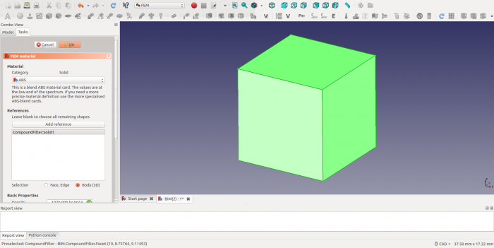
Le matériel(La matière) est assigné Prendre au filet des Régions via un objet SolidMaterial. Dans ces travaux dirigés(didacticiel) nous assignons deux matériels(matières); un pour la Matrice et un pour le Cœur.
Start by selecting the CompoundFilter in the object tree. Then create a SolidMaterial object via menu option "Model > FEM material for solid". Open the dialog and tick the radio button for Solid, press "Add Reference" and select the CompoundFilter object from the Graphical Window. The reference list should now show "CompoundFilter:Solid1", as before. We assign ABS material to the Matrix, with a Young's modules approximately 1% that of steel.
Repeat the above procedure for the Core ("CompoundFilter:Solid2") with the help of the selection macro. This time we assign CalculiX-Steel, which is much stiffer than the ABS material for the Matrix.
Sliding Support
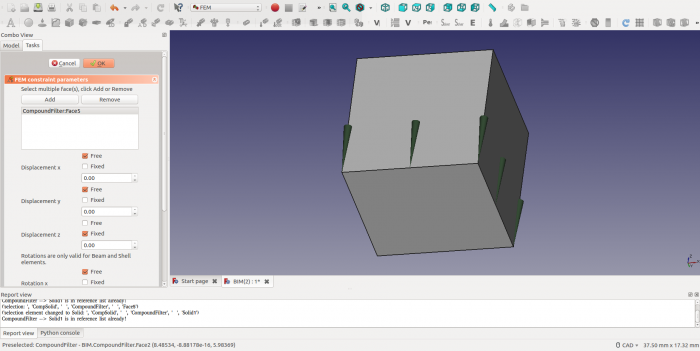
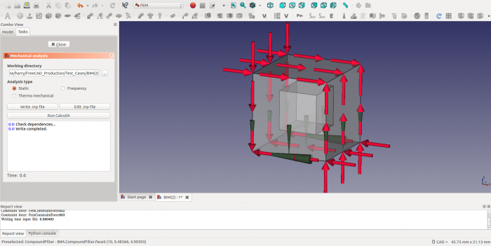
To create a "Simple Shear" condition for the composite block the deformations at the boundaries need to be unconstrained. To achieve this, the block is placed on a sliding support. This leaves three degrees of freedom in the plane of the support (2 translations and a rotation) and those will be constrained later. (Note: as the plane prevents warping of the face, it still induces a minor constraint, which could be eliminated by a different choice of boundary conditions). To create a sliding boundary condition add a FemConstraintDisplacement object (Model > Mechanical Constraints > Constraint displacement). With the dialog box open first select the face to which the boundary conditions is to be applied and then click the Add button. As the block is allowed to slide in the x-y plane, only the "Fixed" radio button for "Displacement z" is selected and the other radio buttons are all left as "Free".
Fixed Nodes
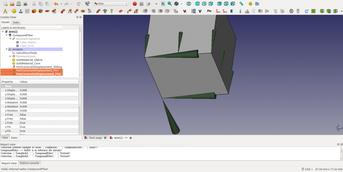
To prevent rigid body motion in the plane of sliding, three independent degrees of freedom need to be eliminated. To achieve this, one vertex in the plane of sliding is constrained in x and y direction (eliminating 2 degrees of freedom) and one vertex is fixed in the x direction (eliminating the last degree of freedom). For this purpose two additional FemConstraintDisplacement objects are created and the result is shown below.
Shear Forces
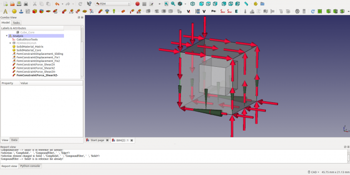
The final step in the Analysis definition is the application of loads. To create a Simple Shear condition, a set of shear loads is applied as shown below. Each load is chosen as 1000 N and considering the directions of application, force and moment equilibrium is achieved for all translation and rotional degrees of freedom. In FC this requires addition of four FemConstraintForce objects (Model > Mechanical Constraints > Constraint force) - one for each face. With the dialog box open first press the Add Reference button and then select the face to which the boundary condition is to be applied (Note: this is a different sequence than with FemConstraintDisplacement). By default, this creates a set of forces perpendicular to the face (i.e. a normal force). To change this to a shear force, press the direction button and select a cube edge that runs in the desired direction. If the resulting force points in opposite direction of what is required, then select the radio button for "Reverse direction".
CalculiX Analysis
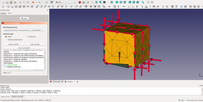
Now all mesh regions, material and boundary conditions have been defined we are ready to analyse the deformation of the block with CalculiX. Activate the Analysis by right clicking "Activate analysis", open the CalculiX dialog by double clicking the CalculiXccxTools object and select a directory for the temporary files created by both FC and CCX. Write CCX Input file and check for any warning or error messages.
After that the analysis can be started by pressing the RunCalculiX button. If all goes well, the CCX output window should show the following messages.
CalculiX Results
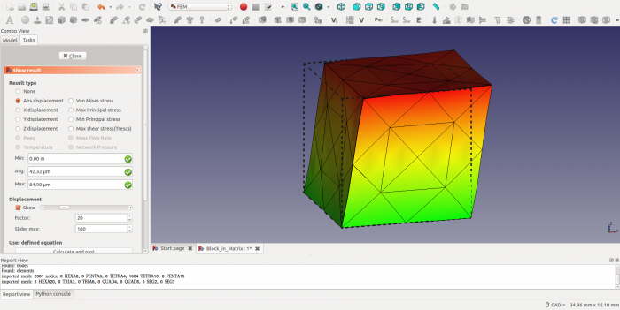
Upon completion of the analysis double click the "CalculiX_static_results" object and select the "Abs displacement" option. The maximum displacement of ~ 0.08mm will show up in the relevant output box. As the maximum displacement is relatively small compared to the dimensions of the block (<1% of the block size), the displacements need to be scaled up. This can be done under the heading "Displacement" by ticking the "Show" radio button and scaling the displacement by a factor of -say- 20. The maximum displacement will now be exaggerated to approximately 20% of the box size. After closing the dialog window, the deformed mesh can be made visible again by highlighting the Result_mesh object and pressing the space bar.
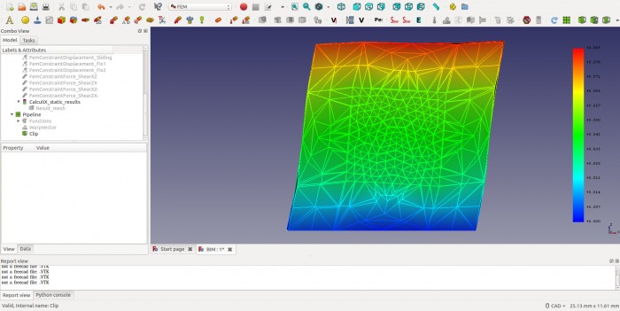
To investigate the deformation of the core we have to slice the block. This can be done by creating a clip filter. To activate this functionality, we first need to create a "post processing pipeline" by highlighting the "CalculiX_static_results" object and choosing "Results > Post Pipeline from Result" from the menu. Next, with the Pipeline selected create a Warp Filter (Results > Warp filter), set Vector=Displacement and Value=20 to scale the displacement and Display Mode = "Surface with Edges", Coloring Field = "Displacement", Vector = "Magnitude" to show colored displacement contours. Press Apply and OK. As a final step add a Clip Filter (Results > Clip filter) and create a plane with origin [5.0,2.5,5.0] and normal [0,1,0], i.e. at a core face with normal in the y-direction. Tick the "Cut Cells" radio button to create a flat surface. As before set Display Mode = "Surface with Edges", Coloring Field = "Displacement", Vector = "Magnitude" to show colored displacement contours. Press Apply and OK. Finally switch the Warp Filter to invisible to only show the cut block.
From the result it is clear that the core remains largely undeformed and helps to resist the deformation of the soft matrix (compare the shear angle of the blue colored part to that of the green colored part). What it also highlights though is that under Simple Shear conditions the faces of the composite block do warp, implying that the sliding boundary condition at the base of the cube does provide an undue constraint.
Further work
The following challenges may be interesting to take up as a further exercise:
1) Correct for the undue constraint imposed by the sliding boundary condition
2) Try and create contact boundary conditions between the core and the matrix to see if separation occurs
The FC file for this tutorial is attached below as a starting point.
https://forum.freecadweb.org/viewtopic.php?f=18&t=26517&start=20
Have fun !
