Drawing tutorial/fr: Difference between revisions
No edit summary |
(Created page with "==== Projections ==== Les projections sont définies comme la représentation visuelle d'un objet sur un plan spécifique, il détermine les propriétés de l'objet visible se...") |
||
| Line 42: | Line 42: | ||
==== Projections ==== |
==== Projections ==== |
||
Les projections sont définies comme la représentation visuelle d'un objet sur un plan spécifique, il détermine les propriétés de l'objet visible selon cette orientation spécifique. |
|||
Projections are defined as the visual representation of an object on a specific plane, it diplays the properties of the object that are visible from that specific orientation. |
|||
===== Orthographic Projections ===== |
===== Orthographic Projections ===== |
||
Revision as of 20:08, 24 September 2017
| Thème |
|---|
| Plans / Dessins |
| Niveau |
| Débutant |
| Temps d'exécution estimé |
| 15 minutes |
| Auteurs |
| Drei |
| Version de FreeCAD |
| 0.16 ou au dessus |
| Fichiers exemples |
| Voir aussi |
| None |
Introduction
Ce tutoriel est destiné à présenter au lecteur le travail de base du de l'atelier Dessin, ainsi que la plupart des outils disponibles pour créer des plans.
Exigences
- FreeCAD version 0.16 ou supérieure
- Le lecteur doit avoir les connaissances de base pour utiliser les ateliers Pièces et Conception de Pièces
- Le lecteur a terminé le Tutoriel Planche à Dessin
Procédure
Préparations
Pour réduire le temps nécessaire à ce tutoriel, il est obligatoire de regrouper des éléments similaires dans Vue Arborescente pour appliquer des opérations en même temps à plusieurs éléments.
Regroupement d' Éléments
- Dans la Vue Arborescente, cliquez avec le bouton droit de la souris sur le nom du document. Dans ce cas Sans nom .
- Sélectionnez Créer un groupe. Vous pouvez modifier le nom du groupe en double-cliquant sur le Vue Arborescente.
- Sélectionnez les éléments que vous souhaitez ajouter et le glisser dans le groupe
Créez les groupes suivants:
- Draft_objects
- Draft_dimensions
- Draft_annotations_text
Exemples de Dessin
Les modèles sont la base de la création des dessins, vous pouvez utiliser les modèles fournis ou créer les vôtres.
- Sélectionnez le menu déroulant à côté de
 Nouveau Dessin A3 Paysage
 - Sélectionnez A4 Paysage
Nous avons maintenant un dossier intitulé 'Page' dans vue Arborescente . Cet objet contiendra tout ce qui concerne le Dessin.
Projections
Les projections sont définies comme la représentation visuelle d'un objet sur un plan spécifique, il détermine les propriétés de l'objet visible selon cette orientation spécifique.
Orthographic Projections
These are used in Engineering to specify the properties of an object that will be machined. There are two common standards: Third Angle and First Angle projections.
For this tutorial, these projections aren't used because our objects only have a meaningful representation in the XY plane.
- Select the object you wish to project into the drawing.
- Select
 Ortho Views
 - Select the type of projection you want to use
- Selec the view you want to add
In the General and Axonometric tabs you can specify the location, scale and separation of each view.
Other Part Projections
It is possible to create custom views of the object.
- Select the object you wish to project into the drawing.
- Select
 Insert a view
 - In the Data tab edit the Direction of the Shape View by altering the values for the X, Y, and Z axes. By default, the values are (0, 0, 1)
You can also alter the location, scale and rotation of the View from within the Data tab. The same can be done for the Orthographic Projections.
Draft Projections
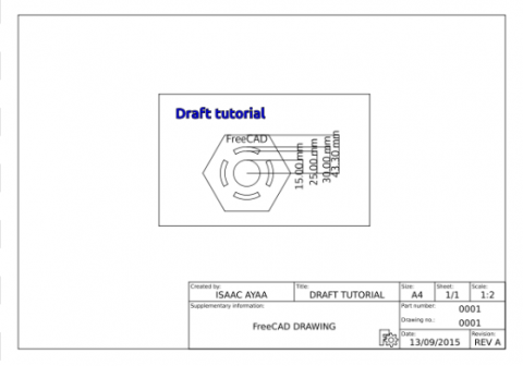
The preferred way to add elements created in the Draft Workbench is with a tool contained in the Draft Workbench designed specifically for this. With this procedure, it is possible to import Dimensions, Annotations, Shapestrings and any other element created whithin the Draft Workbench.
- Switch to the Draft Workbench
- Select the group or elements that you wish to project. In this case Draft_dimensions
- Select
 Drawing
 - Edit the X and Y coordinates to (140,100)
- Set the scale to 0.5
Repeat for each group and set the values to the ones specified above.
Exporting your work
FreeCAD supports the export of SVG and PDF files based on your Drawings
SVG
- Select
 Save sheet
 - Specify the path and name of the exported file
- In the File menu, select Export PDF ...
- Specify the path and name of the exported file
We are now finished with the basic workflow for the Drawing Module.
Recommended Reading
- To learn how to create custom templates see Drawing Template HowTo
- For more information about the tools available check out the Drawing Module page
