Drawing tutorial/de: Difference between revisions
Wurstwasser (talk | contribs) (Created page with "==== Projektionen ==== Projektionen sind definiert als visuelle Repräsentation eines 3D-Objektes auf einer bestimmten Ebene. Es stellt die verschiedenen Eigenschaften des Obj...") |
Wurstwasser (talk | contribs) (Created page with "===== Orthografische Projektionen ===== Diese Art der Projektion wird in den Ingenieurwissenschaften genutzt, um bestimmte Eigenschaften des Objektes, z.B. Maße oder Winkel,...") |
||
| Line 43: | Line 43: | ||
Projektionen sind definiert als visuelle Repräsentation eines 3D-Objektes auf einer bestimmten Ebene. Es stellt die verschiedenen Eigenschaften des Objektes aus Sicht dieser Ebene dar. |
Projektionen sind definiert als visuelle Repräsentation eines 3D-Objektes auf einer bestimmten Ebene. Es stellt die verschiedenen Eigenschaften des Objektes aus Sicht dieser Ebene dar. |
||
===== |
===== Orthografische Projektionen ===== |
||
Diese Art der Projektion wird in den Ingenieurwissenschaften genutzt, um bestimmte Eigenschaften des Objektes, z.B. Maße oder Winkel, vor der Herstellung festzulegen und darzustellen. Dabei gibt es zwei übliche Standards: ''' Dritter Winkel''' und '''Erster Winkel''' Projektionen. |
|||
These are used in Engineering to specify the properties of an object that will be machined. There are two common standards: '''Third Angle''' and '''First Angle''' projections. |
|||
For this tutorial, these projections aren't used because our objects only have a meaningful representation in the XY plane. |
For this tutorial, these projections aren't used because our objects only have a meaningful representation in the XY plane. |
||
Revision as of 20:27, 14 January 2016
| Topic |
|---|
| {{{Topic}}} |
| Level |
| Anfänger |
| Time to complete |
| 15 Minuten |
| Authors |
| Drei |
| FreeCAD version |
| 0.16 oder neuer |
| Example files |
| See also |
| None |
Einleitung
Dieses Tutorial soll den Leser in den Arbeitsbereich Drawing und andere Elemente zum Erstellen von Blaupausen einführen.
Voraussetzungen
- FreeCAD Version 0.16 oder neuer
- Grundlagenwissen über die Arbeitsbereiche Part und PartDesign
- Das Draft tutorial wurde bereits abgeschlossen
Prozedur
Vorbereitungen
Um den Zeitaufwand für dieses Tutorial zu reduzieren, ist es zwingend erforderlich ähnliche Elemente im Modellbaum zu gruppieren, um eine Operation auf mehrere Elemente gleichzeitig anwenden zu können.
Gruppieren von Elementen
- Im Modellbaum einen Rechtsklick auf den Dokumentnamen (Standard: Unbenannt) ausführen.
- Im dann sichtbaren Menü auf Gruppe erstellen klicken und die Gruppe bei Bedarf umbenennen (mit Doppelklick auf die Gruppe).
- Die passenden Elemente im Modellbaum auswählen und bei gedrückter Maustaste in die Gruppe ziehen.
Erstellen Sie folgende Gruppen:
- Draft_objects
- Draft_dimensions
- Draft_annotations_text
Schablonen zeichnen
Schablonen sind die Grundlage für das Erstellen von Zeichnungen, wobei entweder die mitgelieferten Schablonen oder selbst erstellte verwendet werden können.
Wählen Sie im Arbeitsbereich Drawing das Untermenü neben der Schaltfläche A3 landscape ![]() und klicken Sie auf A4 Landschaft (Alternativ über das Menü Zeichnung > Neue Zeichnung einfügen > A4 Landschaft).
und klicken Sie auf A4 Landschaft (Alternativ über das Menü Zeichnung > Neue Zeichnung einfügen > A4 Landschaft).
Im Modellbaum ist nun ein neuer Ordner namens Page zu sehen. Darin werden alle zur Zeichnung gehörenden Elemente vom Programm gespeichert.
Projektionen
Projektionen sind definiert als visuelle Repräsentation eines 3D-Objektes auf einer bestimmten Ebene. Es stellt die verschiedenen Eigenschaften des Objektes aus Sicht dieser Ebene dar.
Orthografische Projektionen
Diese Art der Projektion wird in den Ingenieurwissenschaften genutzt, um bestimmte Eigenschaften des Objektes, z.B. Maße oder Winkel, vor der Herstellung festzulegen und darzustellen. Dabei gibt es zwei übliche Standards: Dritter Winkel und Erster Winkel Projektionen.
For this tutorial, these projections aren't used because our objects only have a meaningful representation in the XY plane.
- Select the object you wish to project into the drawing.
- Select
 Ortho Views
 - Select the type of projection you want to use
- Selec the view you want to add
In the General and Axonometric tabs you can specify the location, scale and separation of each view.
Other Part Projections
It is possible to create custom views of the object.
- Select the object you wish to project into the drawing.
- Select
 Insert a view
 - In the Data tab edit the Direction of the Shape View by altering the values for the X, Y, and Z axes. By default, the values are (0, 0, 1)
You can also alter the location, scale and rotation of the View from within the Data tab. The same can be done for the Orthographic Projections.
Draft Projections
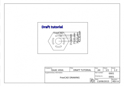
The preferred way to add elements created in the Draft Workbench is with a tool contained in the Draft Workbench designed specifically for this. With this procedure, it is possible to import Dimensions, Annotations, Shapestrings and any other element created whithin the Draft Workbench.
- Switch to the Draft Workbench
- Select the group or elements that you wish to project. In this case Draft_dimensions
- Select
 Drawing
 - Edit the X and Y coordinates to (140,100)
- Set the scale to 0.5
Repeat for each group and set the values to the ones specified above.
Exporting your work
FreeCAD supports the export of SVG and PDF files based on your Drawings
SVG
- Select
 Save sheet
 - Specify the path and name of the exported file
- In the File menu, select Export PDF ...
- Specify the path and name of the exported file
We are now finished with the basic workflow for the Drawing Module.
Recommended Reading
- To learn how to create custom templates see Drawing Template HowTo
- For more information about the tools available check out the Drawing Module page
