Drawing Template : Comment faire
Ce tutoriel vous guidera pas à pas pour créer et modifier un fichier graphique SVG pour l'utiliser comme feuille de dessin au sein de l'atelier Drawing de FreeCAD. À partir de la version 0.14, révision 2995, de FreeCAD l'atelier Drawing va projeter la partie sélectionnée de votre objet sur la feuille en tenant compte de l'ensemble des règles contenues dans le document SVG suivant. Ces règles définissent l'espace de travail, en coordonnées X / Y, où FreeCAD peut afficher le projet et éviter automatiquement les intrusions dans l'espace occupé par le cartouche.
Tout le monde peut s'il le veut partager ses feuilles de conception, toutes les directives de base énoncées dans ce tutoriel devraient être suivies. Il y a des balises pour "Working space" et "Title block" (cartouche) incluses dans le modèle SVG, il ne sont pas inclus dans les anciennes versions de FreeCAD. En incluant ces balises, votre feuille sera entièrement fonctionnelle pour les versions actuelles.
Ce didacticiel commence avec la mise en place d'une page dans Inkscape et crée le dessin de la feuille de base. Puis nous ajouterons un logo pour donner une touche personnelle ou professionnelle à notre travail. Ensuite, nous verrons comment modifier notre nouvelle feuille et quels renseignements elle doit contenir pour être utilisée avec FreeCAD.
Ce tutoriel suppose que vous connaissez les base sur l'utilisation de Inkscape et d'un éditeur de texte.
Les Bases
Mise en page
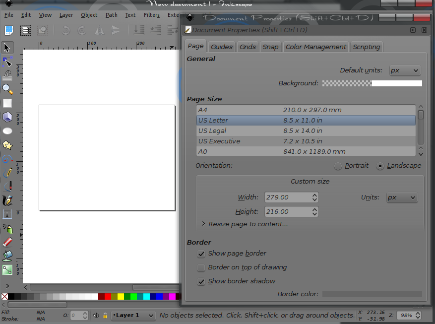
Commençons avec un nouveau document dans Inkscape. En se référant sur la page du Wiki de FreeCAD sur la construction de feuilles de dessin (Template), un pixel = un millimètre. Ce qui signifie que si vous souhaitez créer une feuille de format ANSI A la taille de la page, (format lettre), est de 216 mm X 279 mm, notre feuille devra avoir une taille 216px X 279px. Si vous souhaitez que la feuille ait une orientation paysage, ces chiffres doivent être inversés. Pour ce tutoriel, l'orientation paysage sera utilisée. La feuille est définie comme ayant 279px de large et 216px de haut.
Après avoir exécuté Inkscape, déroulez le menu fichier et sélectionnez Propriétés du Document, vous devriez voir la fenêtre des propriétés du document. Modifiez la largeur et la hauteur comme indiqué et assurez vous que le px (pixel) est l'unité.
Vous devriez maintenant avoir un document Inkscape qui est de 279px large et haute de 216px. Maintenant procédons pour ajouter une bordure.
La Bordure
Ensuite, faites le bord. Quoique non nécessaire, pour ce tutoriel, il est référencé plus tard.
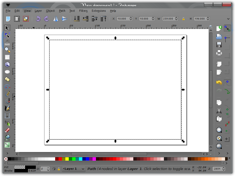
Using the “Draw Bezier curves and straight lines” tool, and selecting the Mode “Create a sequence of paraxial line segments”, make a rectangle within the borders of the document. Once this rectangle is closed, click on the Select and transform objects tool. The rectangle should now show it is selected. If not, use the tool and select it.
Using the Horizontal and Vertical coordinates of selection settings, along with the settings for Width and Height of selection, we will place the border 10 units, (px) in from the document edges. Enter the following. For X enter 10, for Y enter 10, for W enter 259, and for H enter 196. You will see that this set the lower left corner of the rectangle drawn for the border 10 up and 10 over from the lower left corner of the page. Entering the Width and Height sized the rectangle so it is now evenly spaced within the document boundaries.
The Title Block
Next you will make a Title Block. This is where the editable text about the Drawing will be entered when used with FreeCAD. This tutorial will use a simple example. The Title Block can be as simple, or complex as one wishes.
This example Title Block will contain the following, Project Name, Date, Scale, and Author. It will then be placed in the lower right hand corner of the border.
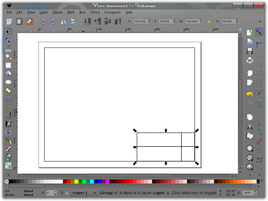
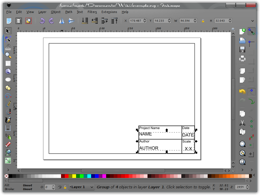
First you start with making a rectangle somewhere within the borders of the document. Make it in the same manner as you did the border. Then divide it into 4 sections as you see fit. Once done, Select the box and the dividing lines, make them a group, and locate it at X =169, Y 10 and size it W=100, H=50, in the same manner done for the border.
Fixed Text
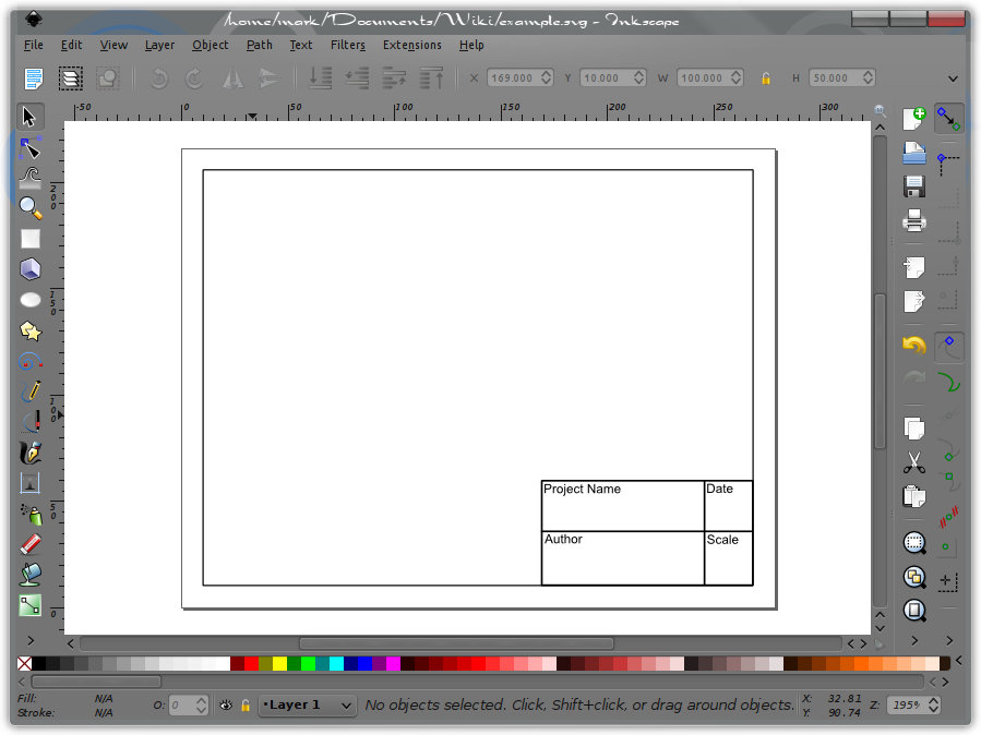
Next, you will add the text blocks that will be fixed within the Title Block. These will be Project Name, Date, Scale, and Author. To do this, select the text tool and click it somewhere in the document. Then simply type in the text, one block to each name. Click the text tool in the document and after selecting the appropriate font size, (size 6 works for this example), type in Project Name. Then move the pointer to a new location and click again, starting a new text block and type in Date. Do the same for Scale, and Author. Now using the select tool the individual text blocks can be moved by dragging and / or the arrow keys to place them into the desired locations.
After the text blocks are placed they should all be selected, along with the title block and made a group. At this point the Title Block and the fixed text are joined together as one.
Editable Text
Now you will add the text blocks that we will want to be editable from within FreeCAD. In the same manner that the fixed text was done, the editable text will be made and placed in their respective locations, You will use the text as follows. NAME, DATE, SCALE, AUTHOR, and make them font size 8. Once the text is placed, select the 4 text fields you wish to be editable and make them a separate group. Do not include them into the same group as the Title Block or Border. For now you are done with the editable text. After the graphical part of the template is done, you will complete the process of making this text editable from within FreeCAD. For now, we will complete this part with adding a little artwork to your template.
Advanced
Adding Artwork
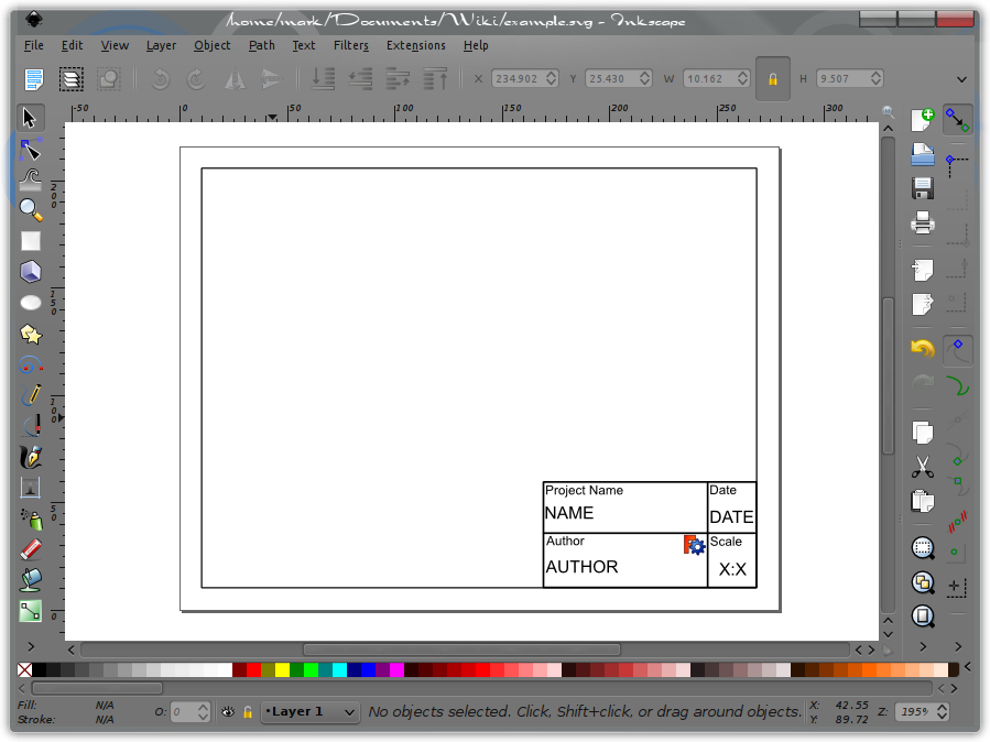
Now that the basic template is done, you can add a bit of artwork to it. This can be whatever you wish. A company or personal graphical logo, a picture or rendering of the project, etc.. For this tutorial the FreeCAD logo, found in the Artwork section of the FreeCAD Wiki will be used. You can simply right click on it and select save image. Once saved, import it into Inkscape. With the image imported into your template, it can be sized and placed where ever you may wish it to be. Adding artwork to your template is as easy as that.
At this point, you can select File, then Save. In this tutorial, the file was simply named example.svg but you may name it whatever you wish.
Once Your Template Is Made
Opening The File With A Text Editor
Once your template is saved, open it with your favorite text editor. This can be something as basic as Windows Notepad or a more complete editor like Kate. In this tutorial, Kate will be used and all screenshots will be of that editor.
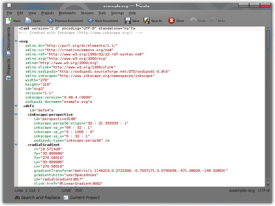
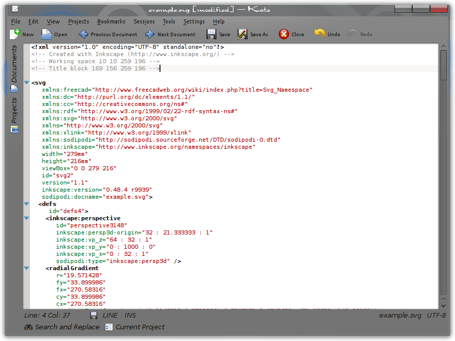
Opening the SVG file with your text editor you will see the following.
The “xmlns:freecad” Tag
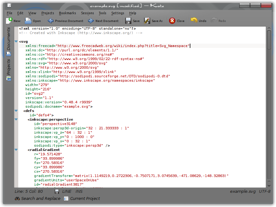
The first thing is to insert the following line into the document. This line is the SVG namespace declaration and must be provided so that all SVG elements are identified as belonging to the SVG namespace.
xmlns:freecad="http://www.freecadweb.org/wiki/index.php?title=Svg_Namespace"
This line is added immediately following the first <svg tag, and in the same margin spacing as the other xmlns entries are placed.
Working space and Title block Tags
The next lines to add will be the Working space and Title block tag. These tags and their usage are defined on the Drawing Templates page. While these tags are not required, newer versions of the FreeCAD Drawing Workbench benefit from them and they will not affect older versions.
The Working space tag is used to define the space that FreeCAD may make projections into. This allows FreeCAD to make automatic projections on the drawing template and stay within the border that has be drawn, or withing any defined space on the page.
The Title block tag is used to define where within the Working space it resides. This information is used by FreeCAD to avoid using that space within the Working space. This can be referred to as Title block avoidance.
If both tags are used, the Working space tag must appear first and be immediately followed by the title block tag. Both tags must also appear before the first <metadata tag. These tags can be placed either at the top, following the <? xml tag or immediately before the <metadata tag. For this tutorial we will place them at the top.
The Working space Tag
The first tag is the Working space tag and is formated as follows.
<!-- Working space X1 Y1 X2 Y2 -->Where X1, Y1, X2, Y2 are defined as:
- X1 is the X axis distance from the left edge of the page to the left side of the Border.
- Y1 is the Y axis distance from the top edge of the page the the top of the Border.
- X2 is the X axis distance from the left edge of the page to the right side of the Border.
- Y2 is the Y axis distance from the top edge of the page the the bottom of the Border.
So for this tutorial template, the Working space tag will be.
<!-- Working space 10 10 259 196 -->The Title block Tag
The next tag will be the Title block tag and is formated as follows:
<!-- Title block X1a Y1a X2a Y2a -->Where X1a, Y1a, X2a, Y2a are defined as:
- X1a is the X axis distance from the left edge of the page to the left side of the Title block
- Y1a is the Y axis distance from the top edge of the page the the top of the Title block
- X2a is the X Axis distance from the left edge of the page to the right side of the Title block
- Y2a is the Y axis distance from the top edge of the page the the bottom of the Title block
- X1a <= X1 or X2a >= X2
- Y1a <= Y1 or Y2a >= Y2
Again, referencing the template created with this tutorial, the title block tag will be as follows:
<!-- Title block 169 156 259 196 -->Placing these two tags, in proper order at the top of the document looks like this:
The freecad:editable Tag
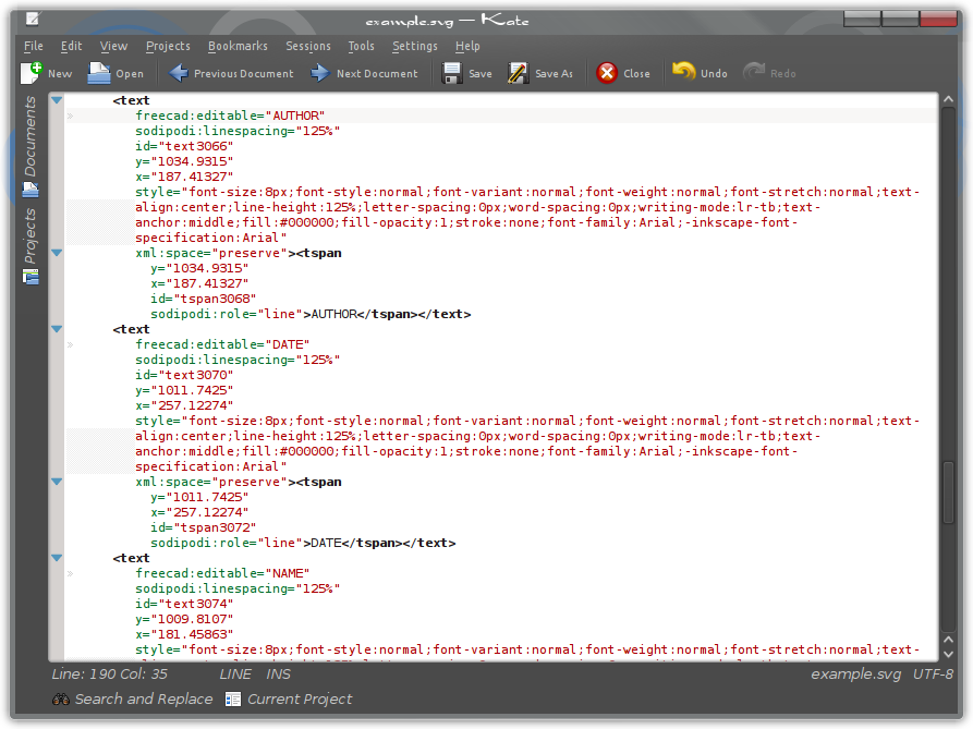
Adding the freecad:editable tags into the SVG document allows FreeCAD to access the defined text blocks for editing. For those blocks of text that you wish to be editable from within FreeCAD, do the following.
Search down through the SVG document until you find the section that contains the text you wish to have editable. When making the template, you placed these in a group, and as a result, they should appear within the document as a group as well. Once this group of text elements is located, you will add the line freecad:editable=” “ to each text block where the text that you wish to make editable is contained within the quote marks. Place them as shown for all four lines of text to be editable.
The DrawingContent Tag
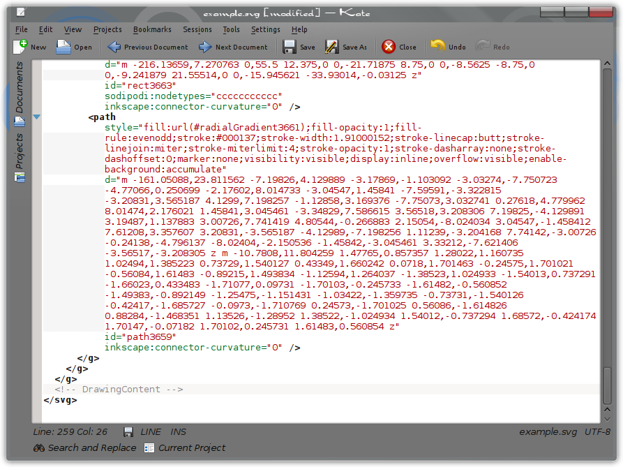
The last tag that is needed in the Template is the DrawingContent tag. Without it, FreeCAD can not access the drawing template. This tag informs FreeCAD where within the document it may write it's projections and other attributes. It is the one tag that must be within the SVG document for the drawing template to work with FreeCAD.
This tag is formated as follows and is inserted just before the last </svg> tag.
<!-- DrawingContent -->That's it. The SVG document can now be saved and used with FreeCAD.
Complete Example Template
Below is the finished SVG template. Sense it is in SVG format, you can save and open it in your text editor for review as reference to this tutorial and the creation of your own templates.
Tools
The two tools used in this tutorial were Inkscape and Kate. They can be found by following the links provided below.
