Drawing ProjectShape: Difference between revisions
Wandererfan (talk | contribs) (cloned from Drawing_ProjectShape/it) |
Renatorivo (talk | contribs) mNo edit summary |
||
| Line 2: | Line 2: | ||
{{GuiCommand|Name=Drawing ProjectShape|Name=Project Shape|Workbenches=[[Drawing Module|Drawing]], Complete|MenuLocation=Drawing → Project shape|Shortcut=|SeeAlso=}} |
{{GuiCommand|Name=Drawing ProjectShape|Name=Project Shape|Workbenches=[[Drawing Module|Drawing]], Complete|MenuLocation=Drawing → Project shape|Shortcut=|SeeAlso=}} |
||
==Description== |
|||
This tool creates a projection of the selected object (Source) in <u>the 3D view</u>. |
This tool creates a projection of the selected object (Source) in <u>the 3D view</u>. |
||
| Line 8: | Line 8: | ||
== Usage == |
|||
{| |
{| |
||
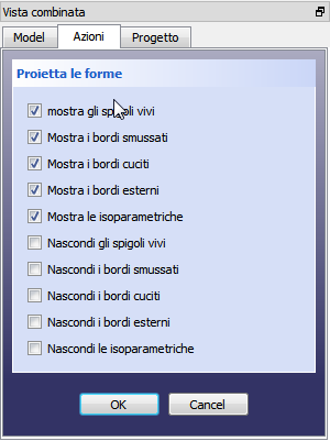
| [[File:ProjectShapeSet_it.png]] |
| [[File:ProjectShapeSet_it.png]] |
||
| Line 16: | Line 17: | ||
# set the desired options in the Task Dialog |
# set the desired options in the Task Dialog |
||
# click {{KEY|OK}} |
# click {{KEY|OK}} |
||
| ⚫ | |||
A projection object ('''objectname_proj''') will be added to the project. For subsequent projections of the same Source object, the projection object will be named '''objectname_projXXX''', where '''XXX''' is a three digit number. |
A projection object ('''objectname_proj''') will be added to the project. For subsequent projections of the same Source object, the projection object will be named '''objectname_projXXX''', where '''XXX''' is a three digit number. |
||
|} |
|} |
||
| ⚫ | |||
| ⚫ | |||
=== Edit an existing projection === |
=== Edit an existing projection === |
||
{| |
{| |
||
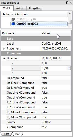
| [[File:ProjectShapeOptions_it.png|right]] |
| [[File:ProjectShapeOptions_it.png|right]] |
||
| |
| |
||
The projection parameters can be edited in the Property editor. |
The projection parameters can be edited in the Property editor. |
||
<br /><br /> |
|||
{{KEY|Base}} |
{{KEY|Base}} |
||
* {{PropertyData|Label}} : |
* {{PropertyData|Label}} : |
||
* {{PropertyData|Placement}} : |
* {{PropertyData|Placement}} : |
||
| ⚫ | |||
{{KEY|Projection}} |
{{KEY|Projection}} |
||
* {{PropertyData|Direction}} : defines the direction of the projection. This is the normal vector of the projection plane. For example, to project the object onto the xy plane, use (0,0,1). To reverse the projection, use negative values. |
* {{PropertyData|Direction}} : defines the direction of the projection. This is the normal vector of the projection plane. For example, to project the object onto the xy plane, use (0,0,1). To reverse the projection, use negative values. |
||
Revision as of 10:03, 18 January 2015
|
Project Shape |
| Menu location |
|---|
| Drawing → Project shape |
| Workbenches |
| Drawing, Complete |
| Default shortcut |
| None |
| Introduced in version |
| - |
| See also |
| None |
Description
This tool creates a projection of the selected object (Source) in the 3D view.


