B-Splines
This page describes how to use B-splines in FreeCAD. It gives also background information what B-splines are and for what applications they are useful.
Motivation
If you know already about B-splines and their application, you can directly continue with section B-splines in FreeCAD.
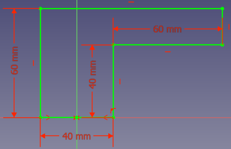
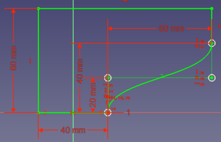
Let's assume you want to design a part that should be produced with a 3D printer. The part must have an edge this way:
You have to print the part in direction of the sketch's bottom to the top. Outer support structures might not be an option. Therefore you need to add a support directly to your part. What options do you have?
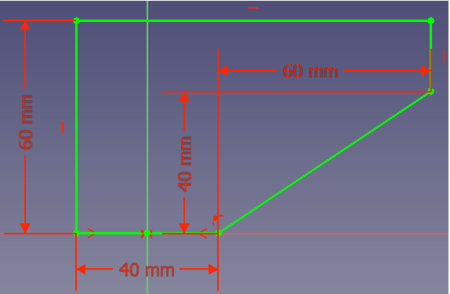
- Option 1: you could add a line from point (0, 20) to point (80, 40):
However this solution needs a lot of volume, thus weight and material.
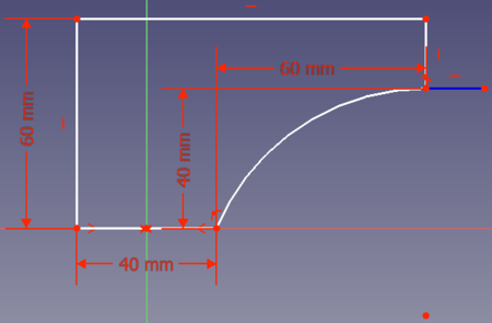
- Option 2: you can connect the two points with an arc of a circle. To save volume, the arc should end tangentially in point (80,40). Then your solution looks like this:
OK. But at the bottom you don't need immediate support.
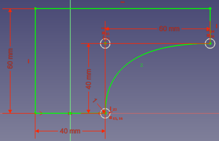
- Option 3: you could save some more volume if the connection between the 2 points is a circle that begins tangentially at (0, 20) and ends tangentially at (80, 40):
So a curve with which you can connect two points tangentially to a reference point can be very useful for constructions. Bézier curves provide this feature.
Bézier curves
Derivation
Bézier curves are polynomials to describe the connection between 2 points. The simplest polynomial connecting 2 points is a line () thus also the linear Bézier curves are linear:
Animation 1: Linear Bézier curve.
However a polynomial becomes first be useful when we can control it. So there should be a point between the 2 endpoints that allows us to define how the endpoints are connected. Like in the above example option 3 the curve is helpful when it starts and ends tangentially to lines crossing the endpoints. And this is a main feature of Bézier curves. So let's add a control point between the 2 endpoints. The curve will start tangentially towards this control point, meaning it is tangential to the line that we can draw between the startpoint and the control point. Going backwards from the endpoint the curve will also be tangential to the line we can draw between the control point and the end point. Animation 2 shows how such a curve looks.
Animation 2: Quadratic Bézier curve. P1 is hereby the control point.
The animation makes clear what the curve basically is - a transition from P0 to P2 by rotating the line P0-P1 to become the line P1-P2. Therefore we get the nice tangential start/end feature.
Such a curve can only be described by a quadratic polynomial. (The number of left-hand/right-hand turns + 1 is the necessary polynomial order to describe such a curve. A quadratic polynomial is a single turn, a cubic polynomial is a combination of a left-hand and right-hand turn, and so on.) Therefore a Bézier curve with one control point is a quadratic (second order) Bézier curve.
Having only control point is often not sufficient. Take the above motivation example. There in option 3 we end the curve tangentially in x-direction. But how can you connect the points (20, 0) and (80, 40) so that the curve ends tangentially in y-direction? To achieve this you need first a right-hand and then a left-hand turn, so a cubic (third order) polynomial. And that means for a Bézier curve that we need (or you can say we gain) a second control point. Animation 3 shows a cubic Bézier curve.
Animation 3: Cubic Bézier curve.
To answer the question, the solution with the tangential y-direction ending for the example is this one:
Math
If you are interested to understand the background math, here are the basics.
A Bézier curve is calculated using this formula:
n is hereby the degree of the curve. So a Bézier curve of degree n is a polygon with order n. The factors are hereby in fact the coordinates of the Bézier curves' control points. For a visualization see this page.
If you are further interested, we have a look at this website with a nicely animated derivation of the math of Bézier curves.
Rules
In the above derivation you might already noticed some "rules" for Bézier curves:
- The polynomial degree is also the degree of the curves.
- If you need turns, you need at least a degree Bézier curve.
- A Bézier curve always begins tangentially to the line between the startpoint and the first control point (and ends tangentially to the line between the last control point and the endpoint).
B-Splines
Basics
If you are interested in more details how a B-Spline is derived from Bézier curves, have a look at these nice explanation videos: this and this.
The first video lists at the beginning the practical problems with Bézier curves. For example that adding or changing a control point changes the whole curve. These problems can be resolved by joining several Bézier curves. The result is a so-called spline, in particular a B-spline (base spline). The first video also explains that a union of quadratic Bézier curves form a uniform quadratic B-spline and that a union of cubic Bézier curves form a uniform cubic B-spline.
From the videos we can also collect useful "rules" for B-splines:
- The first and last control point is the end/start point of the spline.
- Like for Bézier curves, splines always begins tangentially to the line between the startpoint and the first control point (and ends tangentially to the line between the last control point and the endpoint).
- A union of Bézier curves with the degree has needs control points.
- Since one is in most cases working with cubic B-splines we can then state that control points leads to spline segments and in turn segment junction points.
- A B-spline with the degree offers at every point a continuous order derivative.
- For a cubic B-spline this means that the curvature (second order derivative) of the curve does not change when traveling from one segment to the next one. This is a very useful feature as we will later see.
Non-uniform B-splines
B-splines in FreeCAD
FreeCAD offers to create non-uniform B-splines of any degree. By default uniform cubic splines are created, except there are not enough control points to do this. So when you create a B-spline with only 2 control point, you get of course a spline that is single linear Bézier curve, for 3 control points you get a quadratic Bézier curve, first with 5 control points you get a cubic B-spline consisting of 2 Bézier segments.
