Aeroplane/es: Difference between revisions
Emagdalena (talk | contribs) (Created page with "Vamos a añadir más cubos para completar nuestro modelo. Crea un cubo, Selecciona el cubo y cambia su altura a 5mm, longitud a 3mm y ancho a 1mm. Cambia su ubicación a Y: -0.5.") |
Emagdalena (talk | contribs) (Created page with "Ahora necesitamos unir nuestra Fusion al Box001 así que lo haremos del modo rápido. Pulsa sobre el objeto Fusion en la ventana del Proyecto y manteniendo pulsada la tecla CT...") |
||
| Line 43: | Line 43: | ||
Vamos a añadir más cubos para completar nuestro modelo. Crea un cubo, Selecciona el cubo y cambia su altura a 5mm, longitud a 3mm y ancho a 1mm. Cambia su ubicación a Y: -0.5. |
Vamos a añadir más cubos para completar nuestro modelo. Crea un cubo, Selecciona el cubo y cambia su altura a 5mm, longitud a 3mm y ancho a 1mm. Cambia su ubicación a Y: -0.5. |
||
Ahora necesitamos unir nuestra Fusion al Box001 así que lo haremos del modo rápido. Pulsa sobre el objeto Fusion en la ventana del Proyecto y manteniendo pulsada la tecla CTRL pulsa en el cubo Box001. Esto selecciona ambas partes a la vez. Ahora pulsa en el icono [[Image:Part_Fuse.png|32px]] de [[Part_Fuse/es|Fusión]] para obtener Fusion001. |
|||
You should now have a simple aeroplane model. Right-click on Fusion001 and Rename it 'Aeroplane'. |
You should now have a simple aeroplane model. Right-click on Fusion001 and Rename it 'Aeroplane'. |
||
Revision as of 12:42, 8 December 2013
Primeros pasos
Trabajaremos en el Módulo de Piezas - selecciona el módulo de piezas en Vista-> Entorno -> Pieza o desde el selector de entorno.
- Crea un nuevo documento vacío.
- Cambia a la vista axonométrica.
- Activa la visualización del sistema de coordenadas (en el menú Vista).
- Asegúrate de tener visible el selector de vistas (en Vista -> Vistas).
- Crea un cilindro pulsando en el botón
 de Cilindro.
 - Selecciona el cilindro pulsando sobre él en la vista del proyecto.
- Pulsa sobre la pestaña de Datos en la parte inferior de la vista de Proyecto.
Cambia la altura a 20mm. Deja el radio en 2mm.
Pulsa en la ubicación (observa en el pequeño [+]) y se mostrará un botón con tres puntos. Pulsa sobre el (También puedes seleccionar: Menú->Editar->Ubicación). Se mostrará la vista de Tareas.
Si no estas familiarizado con los ejes XYZ entonces juega un poco con los números en el cuadro de Desplazamiento. Después pulsa en el botón de Resetear.
Segundos pasos
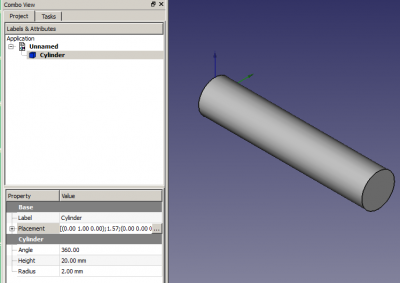
Ahora vamos a rotar el cilindro de modo que esté alineado con el eje X. Para conseguirlo tenemos que hacerlo rotar alrededor del eje Y. El cuadro de rotación debería decir 'Ángulo de rotación con ángulo' así que cambia el eje al Y e incrementa el ángulo hasta que alcance los 90º. Pulsa OK.
Me gustaría practicar con la rotación de la vista en este momento. Deberías ver la 'costura' del cilindro en la parte inferior.
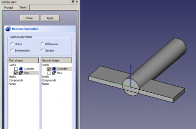
Ahora vamos a añadir y modificar un cubo así que pulsa sobre el icono ![]() del Cubo. Selecciona el cubo en la vista del Proyecto.
Cambia la altura a 1mm, la longitud a 5mm y el ancho a 20mm.
del Cubo. Selecciona el cubo en la vista del Proyecto.
Cambia la altura a 1mm, la longitud a 5mm y el ancho a 20mm.
Pulsa en la ubicación y en el botón con los tres puntos para que se muestre la vista de Tareas. Utilizando el cuadro de Traslación introduce Y: -10 y Z: -1. Pulsa OK
Ahora vamos a fusionar estas dos formas con una operación Booleana. Pulsa en el icono ![]() de Operaciones Booleanas y la vista de Tareas mostrará el selector de Operación Booleana.
de Operaciones Booleanas y la vista de Tareas mostrará el selector de Operación Booleana.
Asegúrate de que esté seleccionada la Unión, y que el cilindro y el cubo están ambos seguidos en el listado de formas. Pulsa en aplicar y luego en Cerrar. Ahora tienes un único objeto denominado Fusion.
Vamos a añadir más cubos para completar nuestro modelo. Crea un cubo, Selecciona el cubo y cambia su altura a 5mm, longitud a 3mm y ancho a 1mm. Cambia su ubicación a Y: -0.5.
Ahora necesitamos unir nuestra Fusion al Box001 así que lo haremos del modo rápido. Pulsa sobre el objeto Fusion en la ventana del Proyecto y manteniendo pulsada la tecla CTRL pulsa en el cubo Box001. Esto selecciona ambas partes a la vez. Ahora pulsa en el icono ![]() de Fusión para obtener Fusion001.
de Fusión para obtener Fusion001.
You should now have a simple aeroplane model. Right-click on Fusion001 and Rename it 'Aeroplane'.
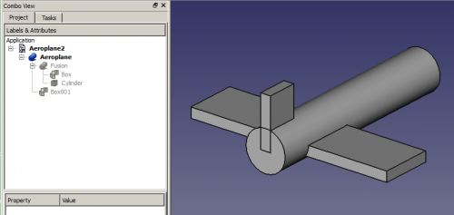
I think the wings need to be moved forward a bit but if I select Aeroplane and try changing its Placement X Translation the whole thing moves. I only want to move the wings so cancel the Placement.
Expand Aeroplane (click on the [+] beside it) and expand Fusion.
Click on Box and get its Placement into Tasks. Notice it already has Y: -10 and Z: -1 in the Translation. Change the X translation to 3 and click on Apply. That's better. Click OK.
Rotations
Click on Aeroplane and get its Placement into Tasks (Other explanation on Placement). In the Rotation section change where it says 'Rotation axis with angle' to 'Euler angles' because they're a lot easier to work with.
-
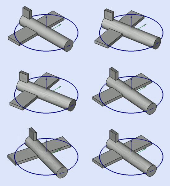
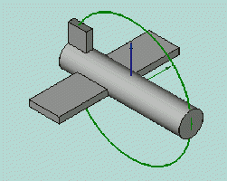
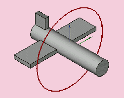
Yaw is the rotation about the Z axis, that is to say a rotation from left to right. (The yaw angle is the Psi ψ).
-
Pitch is rotation about the Y axis, that is to say nose-up and nose-down.
-
Roll is rotation about the X axis, that is to say wing up and down.
However, even here there are some important things to remember:
- Positive Rotations are clockwise when viewed from the Origin outwards along a positive axis. Or to put it another way: Positive Rotations are anticlockwise when viewed from a positive axis towards the Origin.
- Although the three labels are Yaw, Pitch and Roll that's not really what they are. Yaw, Pitch and Roll are references to the body coordinates of an object in 3D space. The labels should be Heading, Elevation and Bank or even Azimuth, Inclination and Bank because thay actually refer to the space coordinates of the 3D system. These are the Tait-Bryan angles. If you want more information then try Euler Angles.
- With the Aeroplane in its present position simple rules apply. Yaw is rotation around the Z axis, ie left and right. Pitch is rotation around the Y axis, ie nose up and down. Roll is rotation around the X axis, ie wings up and down. That's fine to start with but it's not going to be true later!
Have a play with the three YPR numbers. You only need to change things by a few degrees to get the idea. Reset when you finished.
Now we're going to see why the Yaw-Pitch-Roll labels are not really suitable. Change the Roll number to 90°. Yaw should move the nose of the aeroplane up and down and Pitch should move it side to side as viewed from outside the aeroplane which is where we are. Do they? No they don't! Pitch changes the yaw and Yaw changes the pitch. OK, Reset.
So, a better way of thinking about rotations is that Yaw changes your Longitude, Pitch changes your Latitude and Roll changes the direction (NSEW) that you're facing. Or you could check out Axes conventions for other descriptions.
Right, back to work. Change Yaw to 45° and Pitch to -30°. Click on OK to show that the operation has been completed. Now get back the Placement Task and look at the Rotation box. It has reverted to 'Rotation axis with angle' and has some wierd numbers Axis and Angle boxes. Mine had Axis: (0.219493,-0.529904,0.819161) and Angle: 53.65°. The three numbers in brackets are the XYZ components of a unit vector in the 3D space. It is the axis about which our original Aeroplane was rotated to get our final Aeroplane. The angle is how much it was rotated. Clever, huh, but not very friendly! It was Euler who showed that you could combine a series of XYZ rotations into one rotation about one axis.
Here's some more suggestions for playing with the Aeroplane:
- Change the Z Location (and Apply) then change the YPR numbers and see what the effect is. Then try changing the X and Y Locations and rotating.
- Change the X Centre (and Apply) then change the YPR numbers and see what the effect is. Then try changing the Y and Z Centres and rotating.
I hope this little tutorial has helped you to get a feel for rotations.

