Aeroplane
First Steps
We will be working in the Part Workbench - select it from menus via View->Workbench->Part or from the Workbench selector.
- Create a new empty document.
- Switch to Axonometric View.
- Toggle axis cross ON (via View Menu).
- Ensure you have the Combo View showing (via View->Views).
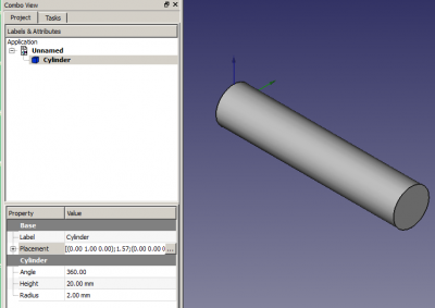
- Create a cylinder by clicking on the Cylinder Icon.
- Select it by clicking on Cylinder in the Project viewer.
- Click on the Data tab at the bottom of the Project viewer.
Change the Height to 20mm. Leave the Radius at 2mm.
Click on Placement (not the little [+]) and a button with three dots will appear. Click on it. The Tasks viewer appears.
If you are unfamiliar with the XYZ axes then have a play with the numbers in the Translation box. When finished playing click on the Reset button.
Second Steps

We are now going to rotate the cylinder so that is lying along the X axis. To do this it needs to be rotated around the Y axis. The Rotation box should say 'Rotation axis with angle' so change the Axis to Y and increment the Angle until it reaches 90. Click on OK.
I like to play with rotating the view at this point (and often!) so by all means do so. You should find the 'seam' of the cylinder on the underside.

We are now going to add and modify a cube so click on the Cube Icon. Select it by clicking on Box in the Project viewer. Change the Height to 1mm, the Length to 5mm and the Width to 20mm.
Click on Placement and the three dots to get the Tasks viewer. Using the Translation box enter Y: -10 and Z: -1. Click on OK
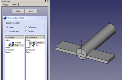
We are now going to merge these two shapes together with a Boolean Operation. Click on the Boolean Operation Icon - it looks like two balls - and the Tasks viewer will display the Boolean Operation selector.
Make sure Union is selected, and that the Cylinder and the Box are each ticked once in the two shape lists. Click on Apply. Click on Close. You now have a single object called Fusion.
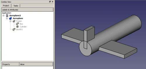
Let's add one more box to finish off our model. Create a Box, Select it and change its Height to 5mm, Length to 3mm and Width to 1mm. Change its Placement by Y: -0.5.
We now need to join our Fusion to Box001 so we'll do it the quick way. Click on Fusion in the Project viewer and CTRL-click on Box001. This selects both parts together. Now click on the Union Icon (the middle of the five icons) to get Fusion001.
You should now have a simple aeroplane model. Right-click on Fusion001 and Rename it 'Aeroplane'.

I think the wings need to be moved forward a bit but if I select Aeroplane and try changing its Placement X Translation the whole thing moves. I only want to move the wings so cancel the Placement.
Expand Aeroplane (click on the [+] beside it) and expand Fusion.
Click on Box and get its Placement into Tasks. Notice it already has Y: -10 and Z: -1 in the Translation. Change the X translation to 3 and click on Apply. That's better. Click OK.
Rotations
Click on Aeroplane and get its Placement into Tasks. In the Rotation section change where it says 'Rotation axis with angle' to 'Euler angles' because they're a lot easier to work with.
Note well: Positive Rotations are clockwise when viewed from the Origin outwards along a positive axis. Or to put it another way: Positive Rotations are anticlockwise when viewed from a positive axis towards the Origin.
Now the reason for creating the Aeroplane becomes clear! Yaw is rotation around the Z axis, ie left and right. Pitch is rotation around the Y axis, ie nose up and down. Roll is rotation around the X axis, ie wings up and down.
