Advanced Attachment OYX/pl: Difference between revisions
(Created page with "Ta demonstracja dotyczy użycia trybu umocowania OYX w celu dostosowania pozycji odniesienia położenia szkicu, jak opisano na stronie Part_EditAttachment/pl|Część: Edyc...") |
(Created page with "Na powyższym rysunku zaprezentowano geometrię użytą w tej demonstracji.") |
||
| Line 17: | Line 17: | ||
Ta demonstracja dotyczy użycia trybu umocowania OYX w celu dostosowania pozycji odniesienia położenia szkicu, jak opisano na stronie [[Part_EditAttachment/pl|Część: Edycja mocowania]], nie jest ona wyczerpująca, ale może pomóc użytkownikom w eksperymentowaniu. |
Ta demonstracja dotyczy użycia trybu umocowania OYX w celu dostosowania pozycji odniesienia położenia szkicu, jak opisano na stronie [[Part_EditAttachment/pl|Część: Edycja mocowania]], nie jest ona wyczerpująca, ale może pomóc użytkownikom w eksperymentowaniu. |
||
Na powyższym rysunku zaprezentowano geometrię użytą w tej demonstracji. |
|||
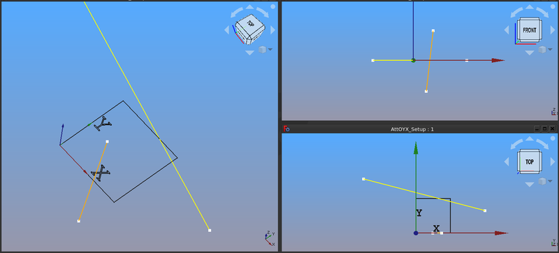
The image above shows the geometry used in this demonstration. |
|||
The lower right frame shows the top view of the scene. Note the scene includes a sketch containing a square and text indicating the vertical (Y), horizontal (X) axes of the sketch. The lower left corner of the square is located at 0,0,0 of the sketch (the origin of the sketch). |
The lower right frame shows the top view of the scene. Note the scene includes a sketch containing a square and text indicating the vertical (Y), horizontal (X) axes of the sketch. The lower left corner of the square is located at 0,0,0 of the sketch (the origin of the sketch). |
||
Revision as of 04:04, 31 March 2022
| Temat |
|---|
| Umocowanie |
| Poziom trudności |
| Średniozaawansowany / zaawansowany |
| Czas wykonania |
| 1 godzina |
| Autorzy |
| drmacro |
| Wersja FreeCAD |
| 0.19 lub nowszy |
| Pliki z przykładami |
| do ustalenia |
| Zobacz również |
| - |
Obiekt w pozycji początkowej
Wprowadzenie
Ta demonstracja dotyczy użycia trybu umocowania OYX w celu dostosowania pozycji odniesienia położenia szkicu, jak opisano na stronie Część: Edycja mocowania, nie jest ona wyczerpująca, ale może pomóc użytkownikom w eksperymentowaniu.
Na powyższym rysunku zaprezentowano geometrię użytą w tej demonstracji.
The lower right frame shows the top view of the scene. Note the scene includes a sketch containing a square and text indicating the vertical (Y), horizontal (X) axes of the sketch. The lower left corner of the square is located at 0,0,0 of the sketch (the origin of the sketch).
The origin of the sketch and the global origin (designated by the red, green and blue axis cross) are the same. In the other frames of the image we can see that the square is at Z=0, so the sketch is in the XY plane.
There are two other sketches which include geometry that will be used to re-position the sketch containing the square. One sketch contains an orange line that is oriented along the global Z axis in the XZ plane. The other sketch contains a yellow line in the XY plane.
Discussion
Attachment mode Align O-Y-X is defined as follows in Part:Attachment: Matches object's origin with first referenced vertex and aligns its vertical and horizontal plane axes toward vertex/along line.. It also notes there are several reference combinations.
- Reference combinations
- Vertex, Vertex, Vertex
- Vertex, Vertex, Edge
- Vertex, Edge, Vertex
- Vertex, Edge, Edge
- Vertex, Vertex
- Vertex, Edge
Lets start with Vertex, Vertex, Vertex.
If we match the definition to the reference:
The first vertex selected will position the origin of the sketch to the selected vertex.
The second vertex selected will align the vertical axis of the sketch (in the demo setup this axis is indicated with Y).
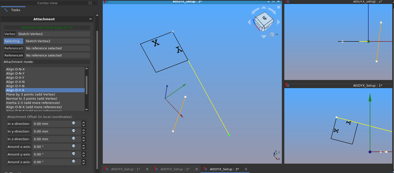
So, if we select the upper left/upper vertex of the yellow edge (as seen in the larger right frame) and the lower/right vertex of the yellow edge the sketch is positioned like this:
- Notes
- The Align O-Y-X is selected in the Attachment dialogue.
- The sketch origin is now at the upper left/upper vertex of the yellow line.
- The Y axis of the sketch is now aligned with the yellow line.
- The Z axis of the sketch is perpendicular to the yellow line.
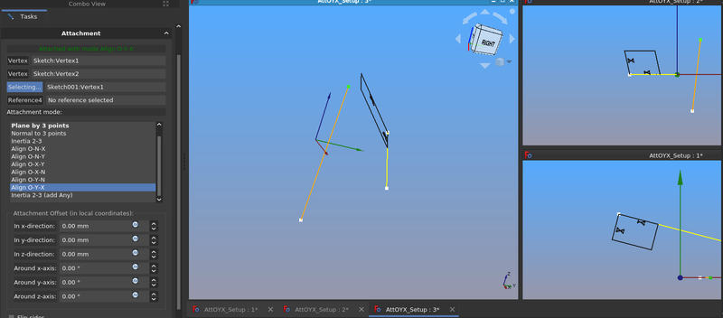
Now if we add a third reference by selecting the upper vertex of the orange edge the scene changes to:
- Notes
- Now the X axis of the sketch is aligned in the direction of the selected vertex of the orange edge.


