A2plus Workbench: Difference between revisions
m (replace "ConstraintPropertiesDialog.jpg" with "A2p_ConstraintPropertiesDialog.png") |
(→Point on Point: refer to the FC glossary) |
||
| Line 39: | Line 39: | ||
==== Point on Point ==== |
==== Point on Point ==== |
||
Select a vertex (point) on each part. The toolbar button [[File:A2p PointIdentity.svg|24px]] adds the constraint {{Variable|pointIdentity}}. It will make the placement of the two points to identical. |
Select a [[Glossary#V|vertex]] (point) on each part. The toolbar button [[File:A2p PointIdentity.svg|24px]] adds the constraint {{Variable|pointIdentity}}. It will make the placement of the two points to identical. |
||
==== Point on Line ==== |
==== Point on Line ==== |
||
Revision as of 20:16, 12 February 2019
Introduction
The A2plus workbench is an external workbench to assemble different parts in FreeCAD...
Installing
The A2plus workbench is an addon to FreeCAD. It can easily be installed via the menu Tools → Addon Manager. A2plus is under active development and will get new features frequently. Therefore you should update it regularly using also the menu Tools → Addon Manager. The A2plus code is hosted and developed on GitHub and can also be installed manually by copying it into FreeCAD's MOD directory.
Getting started
At first switch to the A2plus toolbar in FreeCAD. To create an assembly create a new file in FreeCAD. At first this file needs to be saved. It is recommended (but not necessary) to save it in the same folder of the parts you want to assemble.
Now parts can be added to the assembly by using the toolbar button .
Parts that are already in the assembly can be cloned with the toolbar button .
To edit a part from the assembly, select it in the model tree and use the toolbar button . This will open the part into a new tab in FreeCAD unless the part is already opened in FreeCAD.
To import changes in parts into the assembly click on the toolbar button .
Assembling
Assembling parts is done by adding constraints between parts. After a constraint A2plus will move the parts according to the constraint if possible.<br\>For complex constraints between parts A2plus might fail to solve the constraints. Therefore also have a look at section ?? for strategies to resolve such cases.
Constraints between parts are added by keeping the Ctrl key pressed and selecting an edge or face of two parts. The constraint will be added attached in the model tree to the affected parts.
Keeping the overview
The more parts you add, the more important it is to keep the overview. A2plus therefore offers these tools to move and view parts:
- To move a part around in the assembly, select it in the model tree and use the toolbar button
. When you placed the part where you like it, left-click with the mouse. If the moved part has already constraints the part will be placed accordingly by pressing the toolbar button
because this triggers to resolve all constraints of the assembly.
- To show only certain parts in the assembly, select these parts in the model tree and use the toolbar button
. Alternatively you can hide a certain part by selecting it in the model tree and pressing Space to toggle its visibility.
- To toggle the transparency view of the whole assembly you can use the toolbar button File:A2p ToggleTranparency.svg.
Constraints
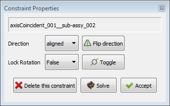
When creating a constraint such a dialog will be displayed after you pressed a constraint toolbar button:
 .
.
For certain constraints it allows you to modify the constraint direction. With the button Solve you can check in advance if this new constraint can be solved by A2plus. If not you can look for alternatives, see section ?? below.
A2plus provides the following constraints:
Point on Point
Select a vertex (point) on each part. The toolbar button adds the constraint pointIdentity. It will make the placement of the two points to identical.
Point on Line
...