Tutorial Draft Forma da Testo
| Argomento |
|---|
| Product design |
| Livello di difficoltà |
| Base |
| Tempo di esecuzione |
| 30 minuti |
| Autori |
| r-frank e vocx |
| Versione di FreeCAD |
| 0.17 o superiore |
| Files di esempio |
| Draft_Shapestring_Text |
| Vedere anche |
| Nessuno |
Introduzione
Questo tutorial è stato originariamente scritto da Roland Frank (†2017, r-frank) ed è stato riscritto e ri-illustrato da vocx.
Questo tutorial descrive un metodo per creare testo 3D e utilizzarlo con oggetti solidi in Part. Si seguano le seguenti indicazioni
- inserire il testo da tracciare con lo strumento
Forma da testo,
- estruderlo in modo che diventi un solido 3D con
Estrudi di Part,
- posizionarlo nello spazio 3D utilizzando Placement e
Sposta di Draft (utilizzare uno schizzo come geometria ausiliaria) e
- incidere il testo applicando in Part una
Sottrazione booleana.
Per utilizzare ShapeString all'interno di PartDesign, il processo è essenzialmente lo stesso dell'ambiente Part, ma ShapeString viene posizionato all'interno del Corpo di PartDesign per estruderlo. Andare alla fine di questo tutorial per ulteriori informazioni.
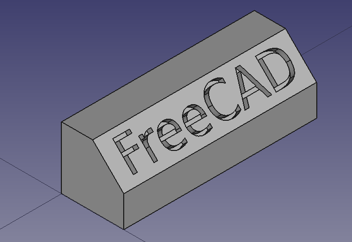
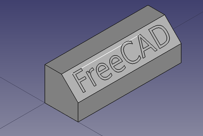
Aspetto finale del testo inciso.
Per disegnare una linea ausiliaria viene utilizzato l'ambiente Sketcher. Maggiori informazioni sugli strumenti di questo workbench sono disponibili in
Impostazione
1. Aprire FreeCAD, creare un nuovo documento vuoto con File → Nuovo e passare a Part.
- 1.1. Premere il pulsante
Isometrica o premere 0 sul tastierino numerico della tastiera per modificare la visualizzazione in isometrica per visualizzare meglio i solidi 3D.
- 1.2. Premere il pulsante
Visualizza tutto ogni volta che si aggiungono oggetti per eseguire la panoramica e lo zoom della Vista 3D in modo che tutti gli elementi siano visibili nella vista.
- 1.3. Tenere premuto Ctrl mentre si clicca per selezionare più elementi. Se si è sbagliato a selezionare qualcosa o si desidera deselezionare tutto, semplicemente fare clic sullo spazio vuoto nella Vista 3D.
Creare la forma di base
2. Inserire una primitva cubo cliccando su Cubo.
- 2.1. Selezionare
Cubonella vista ad albero. - 2.2. Modificare le dimensioni nella scheda Dati dell'editor delle proprietà.
- 2.3. Cambiare Width in
31 mm.
3. Creare uno smusso.
- 3.1. Selezionare il bordo superiore (
Edge6) sulla faccia anteriore delCubonella vista 3D. - 3.2. Cliccare
Smussa.
- 3.3. Nel pannello Smussa spigoli andare su Selezione, scegliere Seleziona spigoli. Come Modalità smusso scegliere
Uguale distanza, quindi impostare Lunghezza su5 mm. - 3.4. Premere OK. Questo creerà un oggetto
Chamfer. - 3.5. Nella vista ad albero, selezionare
Chamfere nella scheda Vista modificare il valore di Line Width in2.0.
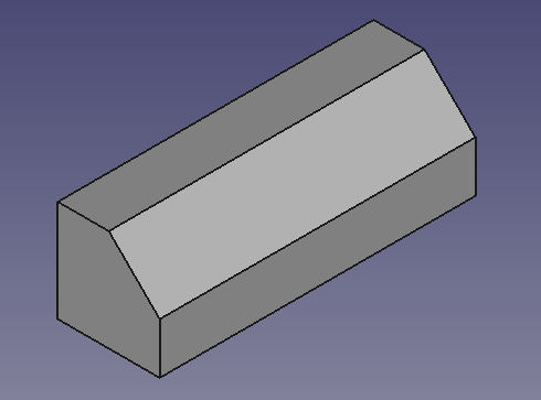
Oggetto di base creato da un cubo e da un'operazione di smusso.
Inserire il testo con lo strumento ShapeString di Draft
4. Passare a Draft.
- 4.1. Assicurarsi che non sia selezionato nulla nella vista ad albero.
- 4.2. Stabilire il piano di lavoro su XY (Dall'alto) facendo clic su
Seleziona piano e cliccando
Dall'alto (XY).
5. Inserire il testo "FreeCAD".
- 5.1. Fare clic su
Forma da testo.
- 5.2. Impostare X in
0 mm. - 5.3. Impostare Y in
0 mm. - 5.4. Impostare Z in
0 mm. - 5.5. Oppure cliccare Reimposta punto.
- 5.6. Scrivere in Stringa
FreeCAD; cambiare Altezza in5 mm. - 5.7. Assicurarsi che Font file punti ad un carattere valido, ad esempio
/usr/share/fonts/truetype/dejavu/DejaVuSans.ttf. Premere i puntini di sospensione ... per aprire la finestra di dialogo del sistema operativo e trovare un font di carattere.- Nota: per ulteriori dettagli sull'utilizzo dei caratteri fare riferimento alla sezione Note in Forma da testo.
- 5.8. Cliccare OK. Questo creerà un oggetto
ShapeString. - 5.9. Ricalcolare il documento cliccando
Aggiorna.
- 5.10. Nella vista ad albero, selezionare
ShapeString, nella scheda Vista modificare il valore di Line Width in2.0. - 5.11. Nella vista ad albero, selezionare
Chamfer, nella scheda Vista cambiare il valore di Visibility infalse, oppure premere Spazio sulla tastiera. Questo nasconderà l'oggetto, così si potrà vedere meglio laShapeString. - 5.12. Per vedere la ShapeString dall'alto, cambiare la vista cliccando
Dall'alto o premere 2 sulla tastiera.
- 5.13. Per ripristinare la vista isometrica, cliccare
Isometrica o premere 0 sulla tastiera.
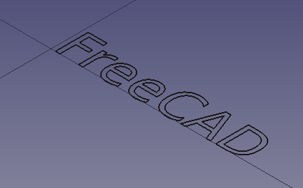
Testo creato come ShapeString, ovvero come raccolta di linee su un piano.
Creare il testo solido 3D
6. Switch back to the Part Workbench.
- 6.1. In the tree view, select
ShapeString, then pressExtrude.
- 6.2. In the Extrude task panel go to Direction, choose Along normal; in Length, set Along to
1 mm; also tick the Create solid option. - 6.3. Press OK. This will create an
Extrudeobject. - 6.4. In the tree view, select
Extrude, in the View tab change the value of Line Width to2.0.
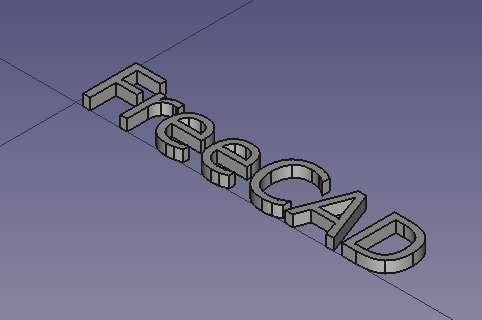
Text created as a ShapeString, and turned into a solid by extrusion.
Inserire lo schizzo ausiliario per il posizionamento
Now we will draw a simple sketch that will be used as auxiliary geometry to position the ShapeString extrusion.
7. In the tree view, select Extrude, and press Space in the keyboard to make it invisible.
8. Switch to the Sketcher Workbench.
9. In the tree view, select Chamfer, and press Space in the keyboard to make it visible.
- 9.1. Choose the sloped face created by the chamfer operation (
Face3). - 9.2. Click on
NewSketch. In the Sketch attachment dialog, select
FlatFace, and press OK. - 9.3. The view should adjust automatically so that the camera is parallel to the selected face.
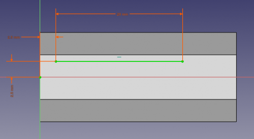
- 9.4. Draw a horizontal line in a general position on top of the face. The length is not important; we are just interested in its position.
- 9.5. Constrain the left endpoint to be
2.5 mmaway from the local X axis and from the local Y axis, usingConstrainDistanceX and
ConstrainDistanceY.
- 9.6. Since the sketch is just an auxiliary object, we don't need to have it fully constrained. You can do this if you wish by assigning a fixed distance, say,
20 mm, again withConstrainDistanceX.
- 9.7. Close the sketch.
Line being created with the sketcher, with constraints.
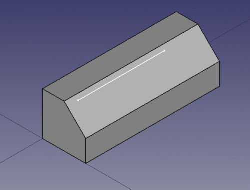
Sketch line created on top of the solid face, to be used as reference guide for positioning the extruded text.
Posizionare il testo 3D nello spazio 3D
10. In the tree view, select Extrude, and press Space in the keyboard to make it visible.
11. With Extrude still selected, in the Data tab of the property editor, click on the Placement value so the ellipsis button ... appears on the right and click on that button.
- 11.1. Tick the option Apply incremental changes.
- 11.2. Change the Rotation to
Rotation axis with angle; Axis toZ(by setting theX,YandZvalues of the axis inputboxes to0,0and1respectively,Zis the third inputbox), and Angle to90 deg, then click on Apply. This will apply a rotation around the Z-axis, and will reset the Angle field to zero. - 11.3. Change the Rotation to
Rotation axis with angle; Axis toY(by setting theX,YandZvalues of the axis inputboxes to0,1and0respectively), and Angle to45 deg, then click on Apply. This will apply a rotation around the Y-axis, and will reset the Angle field to zero. - 11.4. Click on OK to close the dialog.
12. Switch again to the Draft Workbench.
- 12.1. Switch to "Wireframe" draw style with View → Draw style →
Wireframe, or press the
Wireframe button in the view toolbar. This will allow you to see the objects behind other objects.
- 12.2. Make sure the Draft Snap "Snap to endpoint" method is active. This can be done from the menu Draft → Snapping →
Toggle On/Off, and then →
Endpoint, or by pressing the
ToggleSnap and
Snap endpoint buttons in the Snap toolbar.
13. In the tree view, select Extrude.
- 13.1. Click on
Move.
- 13.2. In the 3D view click on the upper left corner point of the
Extrudeobject (1), and then click on the leftmost point in the line drawn with the sketcher (2). - 13.3. If
Snap endpoint is active, as soon as you move the pointer close to a vertex, you should see that it attaches to it exactly.
- Note: if you have problems snapping to vertices, make sure only the
Snap endpoint method is enabled. Having multiple snapping methods active at the same time may make it difficult to select the right feature.
- 13.4. The extruded text should now be inside the body of the
Chamferobject.
The extruded ShapeString should be moved to the position of the sketched line that lies on the face of the base body.
Extruded ShapeString positioned in the Chamfer.
Creare il testo inciso
14. Switch back to the Part Workbench.
- 14.1. Switch to "As is" draw style with View → Draw style →
As is, or press the
As is button in the view toolbar. This will show all objects with the normal shading and color.
- 14.2. In the tree view, select
Sketch, and press Space in the keyboard to make it invisible.
15. In the tree view select Chamfer first, and then Extrude.
- 15.1. Then press
Cut. This will create a
Cutobject. This is the final object. - Note: the order in which you select the objects is important for the cut operation. The base object is selected first, and the subtracting object comes at the end.
- 15.2. In the tree view, select
Cut, in the View tab change the value of Line Width to2.0.
Final model of a filleted cube, with carved text created from a ShapeString, Extrude, and boolean Cut operations.
Engraving 3D text with the PartDesign Workbench
A similar process as described above can be done with the PartDesign Workbench.
- Create the
Draft ShapeString first.
- Create a
PartDesign Body, make it active, and add a base solid by adding primitives, or using a Sketch and extruding it with
PartDesign Pad.
- Move the
ShapeStringobject into the active body. - Attach the
ShapeStringobject to one of the faces of the solid, or to aPartDesign Plane, using
Part EditAttachment.
- Now create a
PartDesign Pad or a
PartDesign Pocket from the
ShapeString, in order to produce an additive or a subtractive feature of the base body, respectively.
See the forum thread, How to use ShapeStrings in PartDesign.
Note
- To create curved text you can use
 Macro FCCircularText.
 - To import text from an SVG file look at the Import text and geometry from Inkscape tutorial.
- Primitives: Box, Cylinder, Sphere, Cone, Torus, Tube, Create primitives, Shape builder
- Creation and modification: Extrude, Revolve, Mirror, Fillet, Chamfer, Make face from wires, Ruled Surface, Loft, Sweep, Section, Cross sections, 3D Offset, 2D Offset, Thickness, Projection on surface, Attachment
- Boolean: Make compound, Explode Compound, Compound Filter, Boolean, Cut, Fuse, Common, Connect, Embed, Cutout, Boolean fragments, Slice apart, Slice, XOR
- Measure: Measure Linear, Measure Angular, Measure Refresh, Clear All, Toggle All, Toggle 3D, Toggle Delta
- Structure tools: Part, Group
- Helper tools: Create body, Create sketch, Edit sketch, Map sketch to face
- Modeling tools
- Datum tools: Create a datum point, Create a datum line, Create a datum plane, Create a local coordinate system, Create a shape binder, Create a sub-object(s) shape binder, Create a clone
- Additive tools: Pad, Revolution, Additive loft, Additive pipe, Additive helix, Additive box, Additive cylinder, Additive sphere, Additive cone, Additive ellipsoid, Additive torus, Additive prism, Additive wedge
- Subtractive tools: Pocket, Hole, Groove, Subtractive loft, Subtractive pipe, Subtractive helix, Subtractive box, Subtractive cylinder, Subtractive sphere, Subtractive cone, Subtractive ellipsoid, Subtractive torus, Subtractive prism, Subtractive wedge
- Transformation tools: Mirrored, Linear Pattern, Polar Pattern, Create MultiTransform, Scaled
- Dress-up tools: Fillet, Chamfer, Draft, Thickness
- Boolean: Boolean operation
- Extras: Migrate, Sprocket, Involute gear, Shaft design wizard
- Context menu: Set tip, Move object to other body, Move object after other object, Appearance, Color per face
- General: Create sketch, Edit sketch, Map sketch to face, Reorient sketch, Validate sketch, Merge sketches, Mirror sketch, Leave sketch, View sketch, View section, Toggle grid, Toggle snap, Configure rendering order, Stop operation
- Sketcher geometries: Point, Line, Arc, Arc by 3 points, Circle, Circle by 3 points, Ellipse, Ellipse by 3 points, Arc of ellipse, Arc of hyperbola, Arc of parabola, B-spline by control points, Periodic B-spline by control points, B-spline by knots, Periodic B-spline by knots, Polyline, Rectangle, Centered rectangle, Rounded rectangle, Triangle, Square, Pentagon, Hexagon, Heptagon, Octagon, Regular polygon, Slot, Fillet, Corner-preserving fillet, Trim, Extend, Split, External geometry, Carbon copy, Toggle construction geometry
- Sketcher constraints:
- Geometric constraints: Coincident, Point on object, Vertical, Horizontal, Parallel, Perpendicular, Tangent, Equal, Symmetric, Block
- Dimensional constraints: Lock, Horizontal distance, Vertical distance, Distance, Radius or weight, Diameter, Auto radius/diameter, Angle, Refraction (Snell's law)
- Constraint tools: Toggle driving/reference constraint, Activate/deactivate constraint
- Sketcher tools: Select unconstrained DoF, Select associated constraints, Select associated geometry, Select redundant constraints, Select conflicting constraints, Show/hide internal geometry, Select origin, Select horizontal axis, Select vertical axis, Symmetry, Clone, Copy, Move, Rectangular array, Remove axes alignment, Delete all geometry, Delete all constraints
- Sketcher B-spline tools: Show/hide B-spline degree, Show/hide B-spline control polygon, Show/hide B-spline curvature comb, Show/hide B-spline knot multiplicity, Show/hide B-spline control point weight, Convert geometry to B-spline, Increase B-spline degree, Decrease B-spline degree, Increase knot multiplicity, Decrease knot multiplicity, Insert knot, Join curves
- Sketcher virtual space: Switch virtual space
- Additional: Sketcher Dialog, Preferences, Sketcher scripting
- Getting started
- Installation: Download, Windows, Linux, Mac, Additional components, Docker, AppImage, Ubuntu Snap
- Basics: About FreeCAD, Interface, Mouse navigation, Selection methods, Object name, Preferences, Workbenches, Document structure, Properties, Help FreeCAD, Donate
- Help: Tutorials, Video tutorials
- Workbenches: Std Base, Arch, Assembly, CAM, Draft, FEM, Inspection, Mesh, OpenSCAD, Part, PartDesign, Points, Reverse Engineering, Robot, Sketcher, Spreadsheet, Surface, TechDraw, Test Framework
- Hubs: User hub, Power users hub, Developer hub
