Translations:PartDesign Bearingholder Tutorial II/15/ro

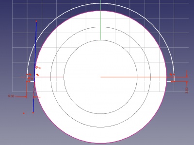
Create a new body and make it active. The sketch for the first pad is shown on the right. It is placed on a datum plane with an offset of 5mm (wall thickness) from the skeleton face marking the side of one of the bearing sealing rings. Because all the important dimensions are taken from the skeleton, there are just three dimensions: The machining allowance (3mm) at the base as an offset to the XY-plane, the 5mm wall thickness from the outer diameter of the skeleton, and the two degrees draft angle. Two create the 5mm dimension, you first need to select the outer circle (radius 45mm) of the skeleton geometry as external geometry in the sketcher, and then put in a construction line constrained tangential to this circle and at an angle of two degrees.