Whiffleball-Anleitung
| Thema |
|---|
| Produktgestaltung |
| Niveau |
| Anfänger |
| Zeit zum Abschluss |
| 30 min |
| Autoren |
| r-frank und vocx |
| FreeCAD-Version |
| 0.17 und höher |
| Beispieldateien |
| WhiffleBall_Tutorial_FCWiki.FCStd |
| Siehe auch |
| None |
Einführung
Dieses Tutorium wurde ursprünglich von Roland Frank (†2017, r-frank) verfasst, und es wurde von vocx neu geschrieben und illustriert.
Dieses Tutorium soll dir vermitteln, wie man die Part Arbeitsbereich benutzt.
Der Part Arbeitsbereich war der erste entwickelte Arbeitsbereich. Sie liefert die grundlegenden geometrischen Elemente, die als Bausteine für andere Arbeitsbereiche verwendet werden können. Der Part Arbeitsbereich ist für die Verwendung in einem herkömmlichen Konstruktiven Festkörpergeometrie (CSG) Arbeitsablauf gedacht. Für einen moderneren Arbeitsablauf mit Skizzen, Blöcken und Formelementen verwende den PartDesign Arbeitsbereich.
Du wirst üben:
- Einfügen von Grundelementen (Primitiven)
- sich ändernde Parameter dieser Grundelementobjekte
- Ändern ihrer Positionierung
- Ausführen Boolesche Operationen
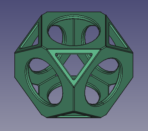
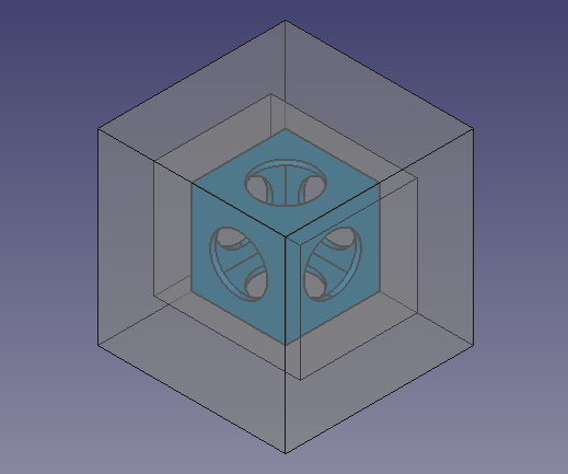
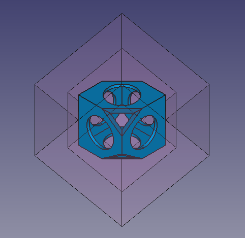
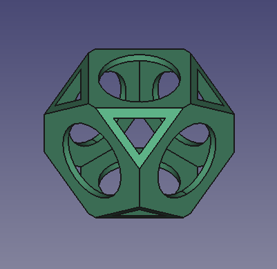
Endgültiges Modell des Wiffleballs
Einrichtung
1. Öffne FreeCAD, erstelle ein neues leeres Dokument mit Datei → Neu, und wechsle zum Part Arbeitsbereich.
- 1.1. Drücke die
Isometrische Ansicht Schaltfläche oder drücke 0 auf dem Ziffernblock deiner Tastatur, um die Ansicht auf isometrisch zu ändern und die 3D Volumenkörper besser zu visualisieren.
- 1.2. Drücke die
Ansicht alles einpassen Schaltfläche wann immer du Objekte zum Schwenken und Zoomen der 3D Ansicht hinzufügst, so dass alle Elemente in der Ansicht zu sehen sind.
- 1.3. Halte Strg gedrückt, währen du klickst, um mehrere Elemente auszuwählen. Wenn du etwas falsch ausgewählt hast oder die Auswahl aufheben möchtest, klicke einfach auf eine leere Stelle in der 3D Ansicht.
Einfügen von Grundelementwürfeln
2. Füge einen Grundelementwürfel ein, indem du auf Kasten klickst.
- 2.1. Wähle
Würfelin der Baumansicht. - 2.2. Ändere die Abmessungen im Daten reiter des Eigenschaftseditors.
- 2.3. Ändere Länge in
90 mm. - 2.4. Ändere Breite in
90 mm. - 2.5. Ändere Höhe in
90 mm.
3. Im Daten reiter des Eigenschaftseditors, klicke auf den Positionierung Wert damit die elliptische Taste ... zur rechten erscheint.
- 3.1. Drücke auf die Ellipse um den Positionierungs dialog zu starten.
- 3.2. Ändere die Übersetzungs Werte.
- 3.3. Ändere X auf
-45 mm. - 3.4. Ändere Y auf
-45 mm. - 3.5. Ändere Z auf
-45 mm. - 3.6. Drücke die OK Schaltfläche um den Dialog zu schließen.
4. Wiederhole den Vorgang und füge einen zweiten, kleineren Würfel ein, indem du auf Kasten klickst.
- 4.1. Der zweite Würfel wird mit dem gleichen Namen, aber mit einer zusätzlichen Nummer zur Unterscheidung des Objekts erstellt.
- 4.2. :4.2. Wähle
Cube001in der Baumansicht, und ändere die Abmessungen und die Positionierung wie beim vorherigen Objekt. - 4.3. Ändere Länge auf
80 mm. - 4.4. Ändere Breite auf
80 mm. - 4.5. Ändere Höhe auf
80 mm. - 4.6. Öffne den Positionierungs dialog.
- 4.7. Ändere X auf
-40 mm. - 4.8. Ändere Y auf
-40 mm. - 4.9. Ändere Z auf
-40 mm. - 4.10. Drücke die OK Schaltfläche um den Dialog zu schließen.
Ändern der visuellen Eigenschaften
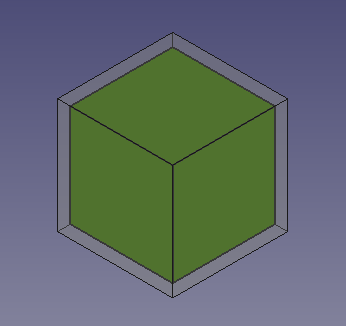
5. Die vorigen Operationen erstellen einen kleineren Würfel in einem größeren Würfel. Um dies zu veranschaulichen, können wir die Ansicht-Eigenschaft im Eigenschaftseditor ändern.
- 5.1. Wähle
Cube001, den kleineren Würfel, in der Baumansicht und ändere die Farbe. Im Ansicht-Reiter, klicke auf den Shape Color-Wert, um den Farbauswahl-Dialog zu öffnen, dann wähle eine grüne Farbe; ändere auch den Wert der Line Width (Linienbreite) auf2.0. - 5.2. Wähle
Cube, den größeren Würfel, in der Baumansicht und ändere die Transparenz. Im Ansicht-Reiter ändere den Wert der Transparency (Transparenz) auf70.
Solid cube inside another solid cube
Einfügen von Grundelementzylindern
6. Insert a primitive cylinder by clicking on Cylinder.
- 6.1. Select
Cylinderin the tree view. - 6.2. Change the dimensions in the Data tab of the property editor.
- 6.3. Change Radius to
27.5 mm. - 6.4. Change Height to
120 mm. - 6.5. Open the Placement dialog.
- 6.6. Change Z to
-60 mm. - 6.7. Press the OK button to close the dialog.
7. Repeat the process, inserting a second cylinder by clicking on Cylinder.
- 7.1. The second cylinder will be created with the same name, but with an additional number to distinguish the object.
- 7.2. Select
Cylinder001in the tree view, and change the dimensions and placement like with the previous object. - 7.3. Change Radius to
27.5 mm. - 7.4. Change Height to
120 mm. - 7.5. Open the Placement dialog.
- 7.6. Change Y to
60 mm. - 7.7. Change the Rotation to
Rotation axis with angle; Axis toX(by setting theX,YandZvalues of the axis inputboxes to0,0and1respectively,Zis the third inputbox), and Angle to90 deg. - 7.8. Press the OK button to close the dialog.
8. Insert another cylinder. This time create a duplicate so that the radius and height don't have to be changed, only its placement.
- 8.1. Select
Cylinder001in the tree view, and go to the menu Edit → Duplicate selection. This will createCylinder002. - 8.2. Open the Placement dialog.
- 8.3. Change X to
-60 mm, and change Y back to0 mm. - 8.4. Change the Rotation to
Rotation axis with angle; Axis toY, and Angle to90 deg. - 8.5. Press the OK button to close the dialog.
Ändern der visuellen Eigenschaften
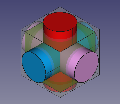
9. The previous operations create three cylinders that intersect with each other, and also intersect the cubes. To visualize this better we can modify the View properties in the property editor.
- 9.1. Select
Cube001, the smaller cube, in the tree view, and change the transparency. In the View tab, change the value of Transparency to70. - 9.2. Select
Cylinder, in the View tab, click on the Shape Color value to open the Select color dialog, then choose a red color. - 9.3. Select
Cylinder001, in the View tab, click on the Shape Color value to open the Select color dialog, then choose a blue color. - 9.4. Select
Cylinder002, in the View tab, click on the Shape Color value to open the Select color dialog, then choose a pink color. - 9.5. Select the three cylinders, in the View tab also change the value of Line Width to
2.0.
Solid cylinders that intersect themselves and the solid cubes.
Verschmelzen und Schneiden
10. In the tree view, select Cube001 (the inner, smaller cube), and the tree cylinders, then press Fuse. This will create a
Fusion object.
11. Then perform a boolean cut of the Cube (larger cube) and the new Fusion object.
- 11.1. In the tree view select
Cubefirst, and thenFusion. - 11.2. Then press
Cut. This will create a
Cutobject. - Note: the order in which you select the objects is important for the cut operation. The base object is selected first, and the subtracting object comes at the end.
- 11.3. If the colors look strange, select the new
Cutobject, go to the View tab, click on the Shape Color value to open the Select color dialog, then choose a gray color; also change the value of Line Width to2.0.
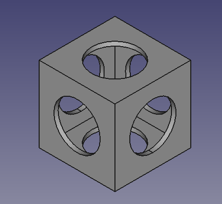
Hohle Form, hergestellt durch Schneiden eines Würfels und dreier Zylinder aus einem größeren Würfel.
Einfügen von Grundelementwürfeln, um die Ecken des Teilkörpers zu schneiden
Now we'll create more cubes that will be used as cutting tools to trim the corners of the previously obtained Cut object.
12. Click on Box.
- 12.1. Select
Cube002in the tree view, and change the dimensions and placement. - 12.2. Change Length to
140 mm. - 12.3. Change Width to
112 mm. - 12.4. Change Height to
112 mm. - 12.5. Open the Placement dialog.
- 12.6. Change X to
-70 mm. - 12.7. Change Y to
-56 mm. - 12.8. Change Z to
-56 mm. - 12.9. Press OK.
13. Click on Box.
- 13.1. Select
Cube003in the tree view, and change the dimensions and placement. - 13.2. Change Length to
180 mm. - 13.3. Change Width to
180 mm. - 13.4. Change Height to
180 mm. - 13.5. Open the Placement dialog.
- 13.6. Change X to
-90 mm. - 13.7. Change Y to
-90 mm. - 13.8. Change Z to
-90 mm. - 13.9. Press OK.
We'll duplicate the previous two objects again to use once more as cutting objects.
14. Select only Cube002 in the tree view, and go to Edit → Duplicate selection. This will create Cube004.
15. Select only Cube003 in the tree view, and go to Edit → Duplicate selection. This will create Cube005.
16. To visualize this better we can modify the View properties in the property editor.
- 16.1. Select the
Cutobject, in the View tab, click on the Shape Color value to open the Select color dialog, then choose a blue color. - 16.2. Select all new cubes,
Cube002,Cube003,Cube004, andCube005, in the View tab, change the value of Transparency to80.
Additional external cubes that will be used as cutting objects for the internal solid.
Schneiden der Ecken 1
17. In the tree view select Cube002 and Cube003.
- 17.1. Open the Placement dialog.
- 17.2. Tick the option Apply incremental changes; notice that all Translation values are reset to zeroes.
- 17.3. Change the Rotation to
Rotation axis with angle; Axis toX, and Angle to45 deg, then click on Apply. This will apply a rotation around the X-axis, and will reset the Angle field to zero. - 17.4. Change the Rotation again, now Axis to
Z, and Angle to45 deg, then click on Apply. This will apply a rotation around the local Z-axis, and will reset the Angle field to zero. - 17.5. Click on OK to close the dialog.
18. In the tree view de-select the objects; then select Cube003 first, the bigger cube, and then Cube002, the smaller cube.
- 18.1. Then press
Cut. This will create
Cut001. This is a hollowed body which intersects the initialCutonly at certain corners.
19. To visualize this better we can modify the View properties in the property editor.
- 19.1. Select
Cube004andCube005, in the View tab, then change the value of Visibility tofalse, or press Space in the keyboard. - 19.2. Select
Cut001, click on the Shape Color value to open the Select color dialog, then choose a red color; also change the value of Transparency to90.
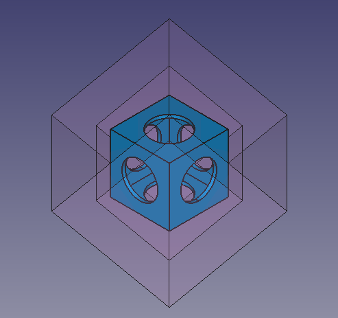
A rotated, hollowed solid, which will be used as a cutting object for some corners of the internal solid.
Schneiden der Ecken 2
20. In the tree view select Cut001, in the View tab, change the value of Visibility to false, or press Space in the keyboard.
21. In the tree view select Cube004 and Cube005, in the View tab, change the value of Visibility to true, or press Space in the keyboard.
- 21.1. Open the Placement dialog.
- 21.2. Tick the option Apply incremental changes; notice that all Translation values are reset to zeroes.
- 21.3. Change the Rotation to
Rotation axis with angle; Axis toX, and Angle to45 deg, then click on Apply. This will apply a rotation around the X-axis, and will reset theAnglefield to zero. - 21.4. Change the Rotation again, now Axis to
Z, and Angle to-45 deg, then click on Apply. This will apply a rotation around the local Z-axis, and will reset the Angle field to zero. - 21.5. Click on OK to close the dialog.
22. In the tree view de-select the objects; then select Cube005 first, the bigger cube, and then Cube004, the smaller cube.
- 22.1. Then press
Cut. This will create
Cut002. This is a hollowed body which intersects the initialCutonly at certain corners.
23. To visualize this better we can modify the View properties in the property editor.
- 23.1. Select
Cut002, click on the Shape Color value to open the Select color dialog, then choose a pink color; also change the value of Transparency to90.
Ein gedrehter ausgehöhlter Volumenkörper, der als Beschnittobjekt für einige Ecken des inneren Volumenkörpers verwendet wird.
Fertigstellung des Modells
24. Make sure all objects are visible. In the tree view select all objects, in the View tab, change the value of Visibility to true, or press Space in the keyboard.
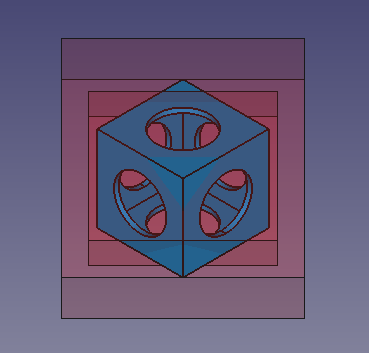
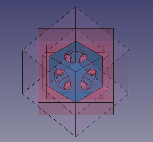
The internal hollowed solid, together with the external objects which will be used to cut it.
25. In the tree view de-select the objects; then select Cut first, and then Cut001.
- 25.1. Then press
Cut. This will create
Cut003.
The internal hollowed solid, cut by Cut001.
26. In the tree view de-select the objects; then select Cut003 first, and then Cut002.
- 26.1. Then press
Cut. This will create
Cut004. This is the final object. - 26.2. Select
Cut004, click on the Shape Color value to open the Select color dialog, then choose a green color; also change the value of Line Width to2.0.
The internal hollowed solid, cut by Cut001 and Cut002. Final model.
27. Real objects don't have perfectly sharp edges or corners, so applying a fillet to the edges can be done to refine the model.
- 27.1. In the tree view, select
Cut004then pressFillet.
- 27.2. In the Fillet edges task panel go to Selection, choose Select edges, and then press All. As Fillet type choose
Constant radius, then set Radius to1 mm. - 24.3. Press OK. This will create a
Filletobject. - 27.4. In the View tab, change the value of Line Width to
2.0.
Final whiffle ball model with fillets applied to the edges.
- Grundkörper: Würfel, Kegel, Zylinder, Kugel, Torus, Grundkörper, Shapebuilder
- Objekte ändern: Boolesche Operationen, Vereinigung, Schnitt, Ausschneiden, Join features, Connect, Embed, Cutout
- Aufteilungswerkzeuge: Boolesche Fragmente, Slice a part, Slice, XOR, Part Defeaturing
- Verbund: Erzeuge Verbund, Verbund auflösen, Compound Filter; Extrudieren, Kanten abrunden, Drehen, Schnitt, Schnitte..., Abschrägen, Spiegelung, Ruled Surface, Sweep, Loft
- Offset-Werkzeuge: 3D Offset, 2D Offset, Dicke, Projection on surface
- Erste Schritte
- Installation: Herunterladen, Windows, Linux, Mac, Zusätzlicher Komponenten, Docker, AppImage, Ubuntu Snap
- Grundlagen: Über FreeCAD, Graphische Oberfläche, Mausbedienung, Auswahlmethoden, Objektname, Programmeinstellungen, Arbeitsbereiche, Dokumentstruktur, Objekteigenschaften, Hilf FreeCAD, Spende
- Hilfe: Tutorien, Video Tutorien
- Arbeitsbereiche: Std Base, Arch, Assembly, CAM, Draft, FEM, Inspection, Mesh, OpenSCAD, Part, PartDesign, Points, Reverse Engineering, Robot, Sketcher, Spreadsheet, Start, Surface, TechDraw, Test Framework, Web
