Navigation Cube/ナビゲーションキューブ
Introduction
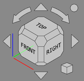
The Navigation Cube gives visual information about the camera orientation in the current 3D view and can be used to change it. By default it is visible and resides in the upper right corner of the view.
ナビゲーションキューブは、次の部分で構成されています。
- Directional Arrows
- Main Navigation Cube
- Mini-cube Menu
All parts, except the axis indicators, can be clicked.
Usage
Main cube
The main cube has 26 faces: 6 main faces, 12 rectangular edge faces (introduced in version 0.20), and 8 corner faces. Clicking any of them will reorient the camera so that its direction is perpendicular to the selected face.
Directional Arrows
6つの方向矢印があります。4つの三角矢印、上、下、左、右に1つずつ。 2つの湾曲した矢印。1つは上の矢印の両側にあります。
Reverse view button
Clicking the round button in the top right corner of the Navigation Cube will rotate the 3D view 180 degrees around the vertical axis of the view.
Mini-cube Menu
ナビゲーションキューブの右下隅には小さなキューブがあります。 この立方体をクリックすると、ビューのタイプを変更するために使用できるメニューが表示されます(直交図、遠近法、等角図)。 そして、「ズームしてフィット」を実行します。
Customization
ナビゲーションキューブの表示を移動する
メインナビゲーションキューブ内の任意の場所でマウスを押してドラッグすると、ナビゲーションキューブ制御構造全体を3D表示内の別の場所に移動できます。 この記事の執筆時点(0.18)では、マウスポインタがメインナビゲーションキューブの端を越えて移動するまで構造は開始されません。
Preferences
The Navigation Cube is controlled by several preferences: Edit → Preferences... → Display → Navigation → Navigation cube. See Preferences Editor.
Advanced parameters
Some advanced Navigation Cube parameters cannot be changed in the Preferences Editor. These parameters can be set manually in the Parameter editor or via the CubeMenu external workbench. Changes will become visible when a new 3D view is created (with Std New, Std Open or Std ViewCreate).
To manually set colors:
- Start the
Parameter editor.
- In the panel on the left browse to BaseApp → Preferences → NaviCube.
- Right-click the panel on the right and select New unsigned item from the context menu.
- Enter the name of one of these colors:
- BorderColor: the lines separating the cube faces, default is
842150655(hex:323232ff). - ButtonColor: all elements around the cube, default is
3806916480(hex:e2e9ef80). - FrontColor: all cube faces, default is
3806916544(hex:e2e9efc0). - HiliteColor: the cube or arrow face that is currently highlighted, default is
2867003391(hex:aae2ffff). - TextColor: the text on the cube faces, default is
255(hex:000000ff).
- BorderColor: the lines separating the cube faces, default is
- The color value must be entered as a 32-bit unsigned integer. Translated to the hexadecimal format this integer has the form
RRGGBBAA. WhereAAstands for the alpha channel (a measure for the transparency), and the other three digit pairs stand for red, green and blue. To convert a hexadecimal value to an unsigned integer you can use the Python console, enter for exampleint("323232ff", 16), or an online service such as this one. - Optionally set more colors.
- Press the Close button.
To manually set the border width:
- Start the
Parameter editor.
- In the panel on the left browse to BaseApp → Preferences → NaviCube.
- Right-click the panel on the right and select New float item from the context menu.
- Enter the name BorderWidth,
default is 1.1. - Enter the width.
- Press the Close button.
- Getting started
- Installation: Download, Windows, Linux, Mac, Additional components, Docker, AppImage, Ubuntu Snap
- Basics: About FreeCAD, Interface, Mouse navigation, Selection methods, Object name, Preferences, Workbenches, Document structure, Properties, Help FreeCAD, Donate
- Help: Tutorials, Video tutorials
- Workbenches: Std Base, Arch, Assembly, CAM, Draft, FEM, Inspection, Mesh, OpenSCAD, Part, PartDesign, Points, Reverse Engineering, Robot, Sketcher, Spreadsheet, Start, Surface, TechDraw, Test Framework, Web
- Hubs: User hub, Power users hub, Developer hub
