Translations:PartDesign Workbench/18/cs
Properties
There are two types of feature properties accessible through tabs at the bottom of the property editor:
- PohledView : properties related to the "visual" display of an object.
- ÚdajeData : properties related to the "physical" parameters of an object.
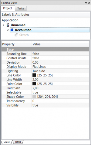
View

Base
- PohledBounding Box : Indicates if a box showing the overall extent of the object is to be displayed. Value False, or True (Default, False).
- PohledControl Point : Indicates if the feature control points are to be displayed. Value False, or True (Default, False).
- PohledDeviation : Sets the accuracy of the polygonal representation of the model in the 3d view (tessellation). Lower values = better quality. The value is in percent of object's size (deviation in mm = (w+h+d)/3*valueInPercent/100, where w,h,d are the bounding box dimensions).
- PohledDisplay Mode :Display mode of the feature, Flat lines, Shaded, Wireframe, Points
 . (Default, Flat lines).
 - PohledLighting : Lighting One side, Two side
 . (Default, Two side).
 - PohledLine Color : Gives the color of the line (edges) (Default, 25, 25, 25).
- PohledLine Width : Gives the thickness of the line (edges) (Default, 2).
- PohledPoint Color : Gives the color of the points (ends of the feature) (Default, 25, 25, 25).
- PohledPoint Size : Gives the size of the points (Default, 2).
- PohledSelectable : Allows selection of the feature. Value False, ou True (Default, True).
- PohledShape Color : Give the color shape (default, 204, 204, 204).
- PohledTransparency : Sets the degree of transparency in the feature of 0 to 100 (Default, 0).
- PohledVisibility : Determines the visibility of the feature (like the bar SPACE). Value False, or True (Default, True).
Data

Base
ÚdajePlacement :
Summary of the data below.
Every feature has a placement that can be controlled through the Data Properties table. It controls the placement of the part with respect to the coordinate system. NOTE: The placement properties do not affect the physical dimensions of the feature, but merely its position in space!
If you select the title Placement ![]() , a button with three small points appears to the right. Clicking this button ..., opens the Tasks_Placement options window.
, a button with three small points appears to the right. Clicking this button ..., opens the Tasks_Placement options window.
ÚdajeAngle :
Specifies the angle to be used with the axis property (below). An angle is set here, and the axis that the angle acts upon is set with the axis property.
The feature is rotated by the specified angle, about the specified axis.
A usage example might be if you created a revolution feature as required, but then needed to rotate the whole feature by some amount, in order to allow it to line-up with another pre-existing feature.
ÚdajeAxis :
This property specifies the axis/axes about which the feature is to be rotated. The exact value of rotation comes from the angle property (above).
This property takes three arguments, which are passed as numbers in the x, y, and z boxes in the tool. Setting a value for more than one of the axes will cause the part to be rotated in each axis, by the angle value multiplied by the value for the axis.
For example, with an angle of 15° set, specifying a value of 1.0 for x, and 2.0 for y will cause the finished part to be rotated 15° in the x-axis AND 30° in the y-axis.
ÚdajePosition :
This property specifies the base point to which all dimensions refer. This takes three arguments, which are passed as numbers to the x, y, and z boxes in the tool. Setting a value for more than one of the boxes will cause the part to be translated by the number of units along the corresponding axis.
ÚdajeLabel :
The Label is the name given to the object (feature), this name can be changed as desired.
PS: The displayed properties can vary, depending on the tool used.