User:DeepSOIC: Difference between revisions
No edit summary |
No edit summary |
||
| (54 intermediate revisions by the same user not shown) | |||
| Line 1: | Line 1: | ||
Mapping modes of the new Attacher |
|||
<translate> |
|||
<!--T:1--> |
|||
{{GuiCommand|Name=Constraint InternalAngle|Workbenches=[[Sketcher Workbench|Sketcher]], [[PartDesign Workbench|PartDesign]]|Shortcut=A|MenuLocation=Sketch → Sketcher constraints → Constrain angle|SeeAlso=[[Constraint Length|Constraint Length]], [[Constraint Perpendicular|Constraint Perpendicular]]}} |
|||
==Mode Deactivated== |
|||
==Description== |
|||
'''References:''' any |
|||
Perpendicular Constraint makes two lines to be perpendicular to each other, or two curves to be perpendicular at their intersection. Lines are treated infinite, and arcs are treated as full circles/ellipses. The constraint is also capable of connecting two curves, forcing them perpendicular at the joint, similarly to [[Constraint Tangent|Tangent Constraint]]. |
|||
'''Action:''' sketch remains where it was. Attachment is disabled. |
|||
==How to use== |
|||
There are four different ways the constraint can be applied: |
|||
# between two curves (available not for all curves) |
|||
# between two endpoints of a curve |
|||
# between a curve and an endpoint of another curve |
|||
# between two curves at user-defined point |
|||
==Mode Translate== |
|||
To apply perpendicular constraint, one should the follow the steps: |
|||
'''References:''' vertex |
|||
* Select two or three entities in the sketch. |
|||
* Invoke the constraint by clicking its icon on the toolbar, or selecting the menu item, or using keyboard shortcut. |
|||
'''Action:''' sketch origin is translated to coincide with the vertex. Sketch orientation doesn't change, and can be modified by changing Placement property. |
|||
===Between two curves (direct perpendicularity)=== |
|||
[[Image:Sketcher ConsraintPerpendicular mode1.png|600px]] |
|||
[[image:Attacher_mode_Translate.png|250px]] |
|||
Two curves will be made perpendicular at point of their intersection (either real, or of curves' extensions), and the point of intersection will be implicit. This mode is applied if two curves were selected. |
|||
'''Accepted selection:''' |
|||
* line + line, circle, arc |
|||
* circle, arc + circle, arc |
|||
If direct perpendicularity between selected curves is not supported (e.g. between a line and an ellipse), a helper point will be added to sketch automatically, and perpendicular-via-point will be applied. |
|||
==Mode ObjectXY== |
|||
Unlike for tangency, it is perfectly fine to reconstruct the point of perpendicularity by creating a point and constraining it to lie on both curves (thus constraining the point to the intersection). |
|||
'''References:''' object |
|||
'''Action:''' sketching plane is XY plane of object's local coordinate system (according to its Placement property). |
|||
===Between two endpoints (point-to-point perpendicularity)=== |
|||
[[Image:Sketcher ConsraintPerpendicular mode2.png|600px]] |
|||
[[image:Attacher_mode_ObjectXY.png|250px]] |
|||
In this mode, the endpoints are made coincident, and the joint is made to be right angle. This mode is applied when two endpoints of two curves were selected. |
|||
'''Accepted selection:''' |
|||
* endpoint of line/arc/arc-of-ellipse + endpoint of line/arc/arc-of-ellipse (i.e., two endpoints of any two curves) |
|||
==Mode ObjectXZ== |
|||
===Between curve and endpoint (point-to-curve perpendicularity)=== |
|||
'''References:''' object |
|||
[[Image:Sketcher ConsraintPerpendicular mode3.png|600px]] |
|||
'''Action:''' like ObjectXY. |
|||
In this mode, an endpoint of one curve is constrained to lie on the other curve, and the curves are forced perpendicular at the point. This mode is applied when a curve and an endpoint of another curve were selected. |
|||
[[image:Attacher_mode_ObjectXZ.png|250px]] |
|||
'''Accepted selection:''' |
|||
* line, circle, arc, ellipse, arc-of-ellipse + endpoint of line/arc/arc-of-ellipse (i.e., any curve + endpoint of any curve) |
|||
==Mode ObjectYZ== |
|||
===Between two curves at point (perpendicular-via-point) (v0.15)=== |
|||
'''References:''' object |
|||
[[Image:Sketcher ConsraintPerpendicular mode4.png|600px]] |
|||
'''Action:''' like ObjectXY. |
|||
In this mode, two curves are made perpendicular, and the point of perpendicularity is tracked. This mode is applied when two curves and a point were selected. |
|||
[[image:Attacher_mode_ObjectYZ.png|250px]] |
|||
'''Accepted selection:''' |
|||
* any line/curve + any line/curve + any point |
|||
"Any point" can be a lone point, or a point of something, e.g. a center of a circle, an endpoint of an arc, or the origin. |
|||
For the constraint to work correctly, the point must be on both curves. So, as the constraint is invoked, the point will be automatically constrained onto both curves ([[Sketcher helper constraint|helper constraints]] will be added, if necessary), and the curves will be forced perpendicular at the point. These [[Sketcher helper constraint|helper constraints]] are plain regular constraints. They can be added manually, or deleted. |
|||
==Mode FlatFace== |
|||
Compared to direct perpendicular, this constraint is slower, because there are mode degrees of freedom involved, but it supports ellipses. |
|||
'''References:''' face or plane |
|||
'''Action:''' legacy. Sketching on a flat face. |
|||
The placement of the point before the constraint is applied is a hint for the solver for where the perpendicularity should be. |
|||
[[image:Attacher_mode_FlatFace.png|250px]] |
|||
==Scripting== |
|||
Perpendicular Constraint can be created from [[macros]] and from the python console by using the following: |
|||
</translate> |
|||
{{Code|code= |
|||
# direct perpendicularity |
|||
Sketch.addConstraint(Sketcher.Constraint('Perpendicular',icurve1,icurve2)) |
|||
==Mode TangentPlane== |
|||
# point-to-point perpendicularity |
|||
'''References:''' face+vertex or vertex+face |
|||
Sketch.addConstraint(Sketcher.Constraint('Perpendicular',icurve1,pointpos1,icurve2,pointpos2)) |
|||
'''Action:''' sketching plane is tangent to surface of face at the point on the surface that is closest to the vertex. If vertex is linked in first, the plane is translated to go through the vertex. If face is first, the plane touches the surface. X axis of sketch is chosen to go along internal face's parametrization. |
|||
# point-to-curve perpendicularity |
|||
Sketch.addConstraint(Sketcher.Constraint('Perpendicular',icurve1,pointpos1,icurve2)) |
|||
[[image:Attacher_mode_TangentPlane.png|250px]] |
|||
# perpendicular-via-point (plain constraint, helpers are not added automatically) |
|||
Sketch.addConstraint(Sketcher.Constraint('PerpendicularViaPoint',icurve1,icurve2,geoidpoint,pointpos)) |
|||
}} |
|||
<translate> |
|||
where: |
|||
:* <tt>Sketch</tt> is a sketch object |
|||
:* <tt>icurve1, icurve2</tt> are two integers identifying the curves to be made perpendicular. The integers are indexes in the sketch (the value, returned by Sketch.addGeometry). |
|||
:* <tt>pointpos1, pointpos2</tt> should be 1 for start point and 2 for end point. |
|||
:* <tt>geoidpoint</tt> and <tt>pointpos</tt> in PerpendicularViaPoint are the indexes specifying the point of perpendicularity. |
|||
</translate> |
|||
==Mode NormalToEdge== |
|||
{{clear}} |
|||
'''References:''' edge or edge+vertex or vertex+edge |
|||
<languages/> |
|||
'''Action:''' sketching plane is normal to the edge at the point of the edge's curve that is closest to the vertex (or defined by MapPathParameter property, if vertex is not linked). The origin of sketch is translated to the vertex if the virtex is first, or kept at where the curve pierces the sketch plane if edge is first. X axis of sketch is chosen automatically. |
|||
[[image:Attacher_mode_NormalToEdge.png|250px]] |
|||
==Mode FrenetNB== |
|||
'''References:''' curved edge OR curved edge+vertex OR vertex+curved edge |
|||
'''Action:''' sketching plane is normal-binormal (NB) axes of Frenet-Serret coordinates at the point of the edge's curve that is closest to the vertex (or defined by MapPathParameter property, if vertex is not linked). The origin of sketch is translated to the vertex if the vertex is first, or kept at the curve if edge is first. This mode is similar to NormalToEdge, except that X axis is well-defined. |
|||
[[image:Attacher_mode_FrenetNB.png|250px]] |
|||
==Mode TrenetTN== |
|||
'''References:''' curved edge OR curved edge+vertex OR vertex+curved edge |
|||
'''Action:''' sketching plane is tangent-normal (TN) axes of Frenet-Serret coordinates at the point of the edge's curve that is closest to the vertex (or defined by MapPathParameter property, if vertex is not linked). The origin of sketch is translated to the vertex if the vertex is first, or kept at the curve if edge is first. Effectively, if the curve is planar, the sketching plane is the plane of the curve. |
|||
[[image:Attacher_mode_FrenetTN.png|250px]] |
|||
==Mode FrenetTB== |
|||
'''References:''' curved edge OR curved edge+vertex OR vertex+curved edge |
|||
'''Action:''' sketching plane is tangent-binormal (TB) axes of Frenet-Serret coordinates at the point of the edge's curve that is closest to the vertex (or defined by MapPathParameter property, if vertex is not linked). The origin of sketch is translated to the vertex if the vertex is first, or kept at the curve if edge is first. |
|||
[[image:Attacher_mode_FrenetTB.png|250px]] |
|||
==Mode Concentric== |
|||
'''References:''' curved edge OR curved edge+vertex OR vertex+curved edge |
|||
'''Action:''' same as FrenetTN, but sketch origin is placed at the center of curvature of the edge. |
|||
[[image:Attacher_mode_Concentric.png|250px]] |
|||
==Mode SectionOfRevolution== |
|||
'''References:''' curved edge OR curved edge+vertex OR vertex+curved edge |
|||
'''Action:''' same as FrenetNB, but sketch origin is placed at the center of curvature of the edge, and Y axis is the axis of osculating circle. Useful to make grooves on bodies of revolution. |
|||
[[image:Attacher_mode_SectionOfRevolution.png|250px]] |
|||
==Mode ThreePointsPlane== |
|||
'''References:''' vertex+vertex+vertex or line+vertex or vertex+line or line+line |
|||
'''Action:''' sketching plane goes through three vertices defined by references. Line is treated as if it is two vertices. |
|||
[[image:Attacher_mode_ThreePointsPlane.png|250px]] |
|||
==Mode ThreePointsNormal== |
|||
'''References:''' vertex+vertex+vertex or line+vertex or vertex+line or line+line |
|||
'''Action:''' sketching plane contains first two vertices, and is normal to the plane defined by three vertices. |
|||
[[image:Attacher_mode_ThreePointsNormal.png|250px]] |
|||
==Mode Folding== |
|||
'''References:''' line+line+line+line |
|||
'''Action:''' specialty mode to fold polyhedra. See picture. It is required that all four lines share an endpoint. It is not required that both leafs to fold together are the same, like on the picture. |
|||
[[image:Attacher_mode_Folding.png|250px]] |
|||
Latest revision as of 17:21, 1 July 2015
Mapping modes of the new Attacher
Mode Deactivated
References: any
Action: sketch remains where it was. Attachment is disabled.
Mode Translate
References: vertex
Action: sketch origin is translated to coincide with the vertex. Sketch orientation doesn't change, and can be modified by changing Placement property.
Mode ObjectXY
References: object
Action: sketching plane is XY plane of object's local coordinate system (according to its Placement property).
Mode ObjectXZ
References: object
Action: like ObjectXY.
Mode ObjectYZ
References: object
Action: like ObjectXY.
Mode FlatFace
References: face or plane
Action: legacy. Sketching on a flat face.
Mode TangentPlane
References: face+vertex or vertex+face
Action: sketching plane is tangent to surface of face at the point on the surface that is closest to the vertex. If vertex is linked in first, the plane is translated to go through the vertex. If face is first, the plane touches the surface. X axis of sketch is chosen to go along internal face's parametrization.
Mode NormalToEdge
References: edge or edge+vertex or vertex+edge
Action: sketching plane is normal to the edge at the point of the edge's curve that is closest to the vertex (or defined by MapPathParameter property, if vertex is not linked). The origin of sketch is translated to the vertex if the virtex is first, or kept at where the curve pierces the sketch plane if edge is first. X axis of sketch is chosen automatically.
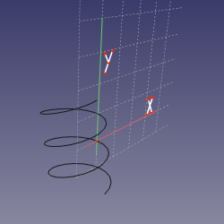
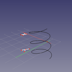
Mode FrenetNB
References: curved edge OR curved edge+vertex OR vertex+curved edge
Action: sketching plane is normal-binormal (NB) axes of Frenet-Serret coordinates at the point of the edge's curve that is closest to the vertex (or defined by MapPathParameter property, if vertex is not linked). The origin of sketch is translated to the vertex if the vertex is first, or kept at the curve if edge is first. This mode is similar to NormalToEdge, except that X axis is well-defined.
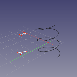
Mode TrenetTN
References: curved edge OR curved edge+vertex OR vertex+curved edge
Action: sketching plane is tangent-normal (TN) axes of Frenet-Serret coordinates at the point of the edge's curve that is closest to the vertex (or defined by MapPathParameter property, if vertex is not linked). The origin of sketch is translated to the vertex if the vertex is first, or kept at the curve if edge is first. Effectively, if the curve is planar, the sketching plane is the plane of the curve.
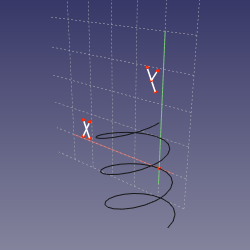
Mode FrenetTB
References: curved edge OR curved edge+vertex OR vertex+curved edge
Action: sketching plane is tangent-binormal (TB) axes of Frenet-Serret coordinates at the point of the edge's curve that is closest to the vertex (or defined by MapPathParameter property, if vertex is not linked). The origin of sketch is translated to the vertex if the vertex is first, or kept at the curve if edge is first.
Mode Concentric
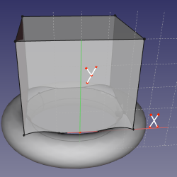
References: curved edge OR curved edge+vertex OR vertex+curved edge
Action: same as FrenetTN, but sketch origin is placed at the center of curvature of the edge.
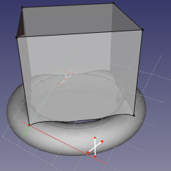
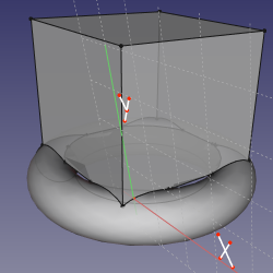
Mode SectionOfRevolution
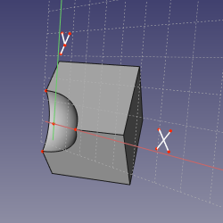
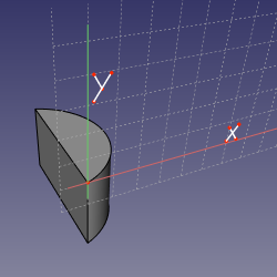
References: curved edge OR curved edge+vertex OR vertex+curved edge
Action: same as FrenetNB, but sketch origin is placed at the center of curvature of the edge, and Y axis is the axis of osculating circle. Useful to make grooves on bodies of revolution.
Mode ThreePointsPlane
References: vertex+vertex+vertex or line+vertex or vertex+line or line+line
Action: sketching plane goes through three vertices defined by references. Line is treated as if it is two vertices.
Mode ThreePointsNormal
References: vertex+vertex+vertex or line+vertex or vertex+line or line+line
Action: sketching plane contains first two vertices, and is normal to the plane defined by three vertices.
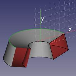
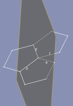
Mode Folding
References: line+line+line+line
Action: specialty mode to fold polyhedra. See picture. It is required that all four lines share an endpoint. It is not required that both leafs to fold together are the same, like on the picture.
