Surface BlendCurve: Difference between revisions
(Created page with "<languages/> <translate> {{Docnav |Fill boundary curves | |Surface |IconL=Surface_CurveOnMesh.svg |IconR= |IconC=Workbench_Surface.svg }} {{GuiCommand |Name=Surface Blend Curve |MenuLocation=Surface → Blend Curve |Workbenches=Surface |Version=0.21 }} ==Description== {{Button|16px Surface Blend Curve}} creates a Bezier curve between two edges, with desi...") |
(added reference to Curves_Workbench, complete the way to launch the command) |
||
| (12 intermediate revisions by 3 users not shown) | |||
| Line 2: | Line 2: | ||
<translate> |
<translate> |
||
<!--T:27--> |
|||
{{Docnav |
{{Docnav |
||
|[[Surface_CurveOnMesh| |
|[[Surface_CurveOnMesh|CurveOnMesh]] |
||
| |
| |
||
|[[Surface_Workbench|Surface]] |
|[[Surface_Workbench|Surface]] |
||
| Line 11: | Line 12: | ||
}} |
}} |
||
<!--T:28--> |
|||
{{GuiCommand |
{{GuiCommand |
||
|Name=Surface |
|Name=Surface BlendCurve |
||
|MenuLocation=Surface → Blend Curve |
|MenuLocation=Surface → Blend Curve |
||
|Workbenches=[[Surface_Workbench|Surface]] |
|Workbenches=[[Surface_Workbench|Surface]] |
||
| Line 18: | Line 20: | ||
}} |
}} |
||
==Description== |
==Description== <!--T:29--> |
||
<!--T:30--> |
|||
{{Button|[[File: |
{{Button|[[File:Surface_BlendCurve.svg|16px]] [[Surface_BlendCurve|Surface Blend Curve]]}} creates a Bezier curve between two edges, with desired continuity. |
||
<!--T:31--> |
|||
The base geometry can belong to curves created with the [[Draft_Workbench|Draft Workbench]] or the [[Sketcher_Workbench|Sketcher Workbench]], but can also belong to solid objects such as those created with the [[Part_Workbench|Part Workbench]]. |
The base geometry can belong to curves created with the [[Draft_Workbench|Draft Workbench]] or the [[Sketcher_Workbench|Sketcher Workbench]], but can also belong to solid objects such as those created with the [[Part_Workbench|Part Workbench]]. |
||
</translate> |
</translate> |
||
[[File: |
[[File:Surface_BlendCurve_G3_example.png|400px]] |
||
[[File:Surface_BlendCurve_Comb.png|400px]] |
|||
[[File:Surface BlendCurve Comb.png|400px|Surface Blend Curve joining 2 edges with G3 conitnuity and curvature comb]] |
|||
<translate> |
<translate> |
||
<!--T:32--> |
|||
{{Caption|Surface Blend Curve joining 2 edges with G3 continuity. Curvature comb is smooth at contact points.}} |
{{Caption|Surface Blend Curve joining 2 edges with G3 continuity. Orange polygon represent the control points. Curvature comb (from [[Curves_Workbench|Curves addon]]) is smooth at contact points.}} |
||
==Usage== |
==Usage== <!--T:33--> |
||
<!--T:34--> |
|||
# Select two edges in the [[3D_view|3D view]] |
# Select two edges in the [[3D_view|3D view]] |
||
# There are several ways to invoke the command: |
|||
# Press the {{Button|[[ |
#* Press the {{Button|[[Image:Surface_BlendCurve.svg|16px]] [[Surface_BlendCurve|Surface Blend Curve]]}} button. |
||
#* Select the {{MenuCommand|Surface → [[Image:Surface_BlendCurve.svg|16px]] Blend Curve}} option from the menu. |
|||
# Adjust the curve shape in the object Data properties |
# Adjust the curve shape in the object Data properties |
||
| Line 39: | Line 47: | ||
<!--T:18--> |
<!--T:18--> |
||
A [[Surface_BlendCurve|Surface Blend Curve]] |
A [[Surface_BlendCurve|Surface Blend Curve]] is derived from the basic [[Part_Feature|Part Feature]] ({{incode|Part::Feature}} class, through the {{incode|Part::Spline}} subclass), therefore it shares all the latter's properties. |
||
<!--T:19--> |
<!--T:19--> |
||
| Line 46: | Line 54: | ||
=== Data === <!--T:20--> |
=== Data === <!--T:20--> |
||
<!--T:35--> |
|||
{{TitleProperty|Blend Curve}} |
{{TitleProperty|Blend Curve}} |
||
<!--T:36--> |
|||
* {{PropertyData|Start Edge| |
* {{PropertyData|Start Edge|LinkSub}}: First input edge. |
||
* {{PropertyData|Start Continuity|Integer}}: Geometric continuity value |
* {{PropertyData|Start Continuity|Integer}}: Geometric continuity value |
||
* {{PropertyData|Start Parameter|Float}}: Normalized parameter along edge; from {{Value|0.0}}(edge start) to {{Value|1.0}}(edge end). |
* {{PropertyData|Start Parameter|Float}}: Normalized parameter along edge; from {{Value|0.0}}(edge start) to {{Value|1.0}}(edge end). |
||
* {{PropertyData|Start Size|Float}}: Size of the tangent. |
* {{PropertyData|Start Size|Float}}: Size of the tangent. |
||
* {{PropertyData|End Edge| |
* {{PropertyData|End Edge|LinkSub}}: Second input edge. |
||
* {{PropertyData|End Continuity|Integer}}: Geometric continuity value |
* {{PropertyData|End Continuity|Integer}}: Geometric continuity value |
||
* {{PropertyData|End Parameter|Float}}: Normalized parameter along edge; from {{Value|0.0}}(edge start) to {{Value|1.0}}(edge end). |
* {{PropertyData|End Parameter|Float}}: Normalized parameter along edge; from {{Value|0.0}}(edge start) to {{Value|1.0}}(edge end). |
||
* {{PropertyData|End Size|Float}}: Size of the tangent. |
* {{PropertyData|End Size|Float}}: Size of the tangent. |
||
=== View === |
=== View === <!--T:37--> |
||
<!--T:38--> |
|||
{{TitleProperty|Base}} |
{{TitleProperty|Base}} |
||
<!--T:39--> |
|||
* {{PropertyView|Control Points|Bool}}: it defaults to {{FALSE}}; if set to {{TRUE}}, it will show an overlay with the control points of the curve. |
* {{PropertyView|Control Points|Bool}}: it defaults to {{FALSE}}; if set to {{TRUE}}, it will show an overlay with the control points of the curve. |
||
== Scripting == |
== Scripting == <!--T:40--> |
||
<!--T:26--> |
<!--T:26--> |
||
{{Emphasis|See also:}} [[FreeCAD_Scripting_Basics|FreeCAD Scripting Basics]]. |
{{Emphasis|See also:}} [[FreeCAD_Scripting_Basics|FreeCAD Scripting Basics]]. |
||
<!--T: |
<!--T:41--> |
||
The |
The Blend Curve tool can be used in [[Macros|macros]] and from the [[Python|Python]] console by adding the {{incode|Surface::FeatureBlendCurve}} object. |
||
* The edges to be used to define the |
* The edges to be used to define the curve must be assigned as [[LinkSub|LinkSub]] to the {{incode|StartEdge}} and {{incode|EndEdge}} properties of the object. |
||
* |
* All objects with edges need to be computed before they can be used as input for the properties of the Blend Curve object. |
||
* All objects with edges need to be computed before they can be used as input for the properties of the Filling object. |
|||
</translate> |
</translate> |
||
| Line 81: | Line 92: | ||
doc = App.newDocument() |
doc = App.newDocument() |
||
points1 = [App.Vector(-20, -20, 0), App.Vector(-20, -8, 0), App.Vector(-17, 7, 0), App.Vector(-18, 25, 0)] |
|||
b = App.Vector(-18, 25, 0) |
|||
c = App.Vector(60, 26, 0) |
|||
d = App.Vector(33, -20, 0) |
|||
points1 = [a, App.Vector(-20, -8, 0), App.Vector(-17, 7, 0), b] |
|||
obj1 = Draft.make_bspline(points1) |
obj1 = Draft.make_bspline(points1) |
||
points2 = [ |
points2 = [App.Vector(60, 26, 0), App.Vector(37, 4, 0), App.Vector(33, -20, 0)] |
||
obj2 = Draft.make_bspline(points2) |
obj2 = Draft.make_bspline(points2) |
||
points3 = [c, App.Vector(37, 4, 0), d] |
|||
obj3 = Draft.make_bspline(points3) |
|||
points4 = [d, App.Vector(-2, -18, 0), a] |
|||
obj4 = Draft.make_bspline(points4) |
|||
doc.recompute() |
doc.recompute() |
||
bcurve = doc.addObject("Surface::FeatureBlendCurve","BlendCurve") |
|||
bcurve.StartEdge = (obj1, 'Edge1') |
|||
bcurve.EndEdge = (obj2, 'Edge1') |
|||
bcurve.EndParameter = 1.00 |
|||
(obj3, "Edge1"), |
|||
bcurve.StartSize = -5.00 |
|||
(obj4, "Edge1")] |
|||
bcurve.EndSize = -5.00 |
|||
doc.recompute() |
|||
# --------------------------------------------------------- |
|||
points_spl = [App.Vector(-10, 0, 2), |
|||
App.Vector(4, 0, 7), |
|||
App.Vector(18, 0, -5), |
|||
App.Vector(25, 0, 0), |
|||
App.Vector(30, 0, 0)] |
|||
aux_edge = Draft.make_bspline(points_spl) |
|||
doc.recompute() |
|||
surf.UnboundEdges = [(aux_edge, "Edge1")] |
|||
doc.recompute() |
|||
# --------------------------------------------------------- |
|||
aux_v1 = Draft.make_line(App.Vector(-13, -12, 5), |
|||
App.Vector(-13, -12, -5)) |
|||
aux_v2 = Draft.make_line(App.Vector(-3, 18, 5), |
|||
App.Vector(-3, 18, -5)) |
|||
doc.recompute() |
|||
surf.Points = [(aux_v1, "Vertex2"), |
|||
(aux_v2, "Vertex1")] |
|||
doc.recompute() |
doc.recompute() |
||
}} |
}} |
||
| Line 132: | Line 112: | ||
<!--T: |
<!--T:42--> |
||
{{Docnav |
{{Docnav |
||
|[[Surface_CurveOnMesh|CurveOnMesh]] |
|||
| |
| |
||
|[[Surface_GeomFillSurface|Fill boundary curves]] |
|||
|[[Surface_Workbench|Surface]] |
|[[Surface_Workbench|Surface]] |
||
|IconL= |
|IconL=Surface_CurveOnMesh.svg |
||
|IconR= |
|IconR= |
||
|IconC=Workbench_Surface.svg |
|IconC=Workbench_Surface.svg |
||
}} |
}} |
||
Latest revision as of 20:48, 2 June 2023
|
|
| Menu location |
|---|
| Surface → Blend Curve |
| Workbenches |
| Surface |
| Default shortcut |
| None |
| Introduced in version |
| 0.21 |
| See also |
| None |
Description
Surface Blend Curve creates a Bezier curve between two edges, with desired continuity.
The base geometry can belong to curves created with the Draft Workbench or the Sketcher Workbench, but can also belong to solid objects such as those created with the Part Workbench.
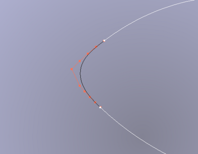
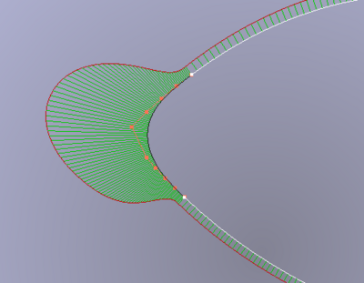
Surface Blend Curve joining 2 edges with G3 continuity. Orange polygon represent the control points. Curvature comb (from Curves addon) is smooth at contact points.
Usage
- Select two edges in the 3D view
- There are several ways to invoke the command:
- Press the
Surface Blend Curve button.
- Select the Surface →
Blend Curve option from the menu.
- Press the
- Adjust the curve shape in the object Data properties
Properties
A Surface Blend Curve is derived from the basic Part Feature (Part::Feature class, through the Part::Spline subclass), therefore it shares all the latter's properties.
In addition to the properties described in Part Feature, the Surface Blend Curve has the following properties in the property editor.
Data
Blend Curve
- DataStart Edge (
LinkSub): First input edge. - DataStart Continuity (
Integer): Geometric continuity value - DataStart Parameter (
Float): Normalized parameter along edge; from0.0(edge start) to1.0(edge end). - DataStart Size (
Float): Size of the tangent. - DataEnd Edge (
LinkSub): Second input edge. - DataEnd Continuity (
Integer): Geometric continuity value - DataEnd Parameter (
Float): Normalized parameter along edge; from0.0(edge start) to1.0(edge end). - DataEnd Size (
Float): Size of the tangent.
View
Base
- ViewControl Points (
Bool): it defaults tofalse; if set totrue, it will show an overlay with the control points of the curve.
Scripting
See also: FreeCAD Scripting Basics.
The Blend Curve tool can be used in macros and from the Python console by adding the Surface::FeatureBlendCurve object.
- The edges to be used to define the curve must be assigned as LinkSub to the
StartEdgeandEndEdgeproperties of the object. - All objects with edges need to be computed before they can be used as input for the properties of the Blend Curve object.
import FreeCAD as App
import Draft

doc = App.newDocument()

points1 = [App.Vector(-20, -20, 0), App.Vector(-20, -8, 0), App.Vector(-17, 7, 0), App.Vector(-18, 25, 0)]
obj1 = Draft.make_bspline(points1)

points2 = [App.Vector(60, 26, 0), App.Vector(37, 4, 0), App.Vector(33, -20, 0)]
obj2 = Draft.make_bspline(points2)

doc.recompute()

bcurve = doc.addObject("Surface::FeatureBlendCurve","BlendCurve")
bcurve.StartEdge = (obj1, 'Edge1')
bcurve.EndEdge = (obj2, 'Edge1')
bcurve.EndParameter = 1.00
bcurve.StartSize = -5.00
bcurve.EndSize = -5.00

doc.recompute()
- Getting started
- Installation: Download, Windows, Linux, Mac, Additional components, Docker, AppImage, Ubuntu Snap
- Basics: About FreeCAD, Interface, Mouse navigation, Selection methods, Object name, Preferences, Workbenches, Document structure, Properties, Help FreeCAD, Donate
- Help: Tutorials, Video tutorials
- Workbenches: Std Base, Assembly, BIM, CAM, Draft, FEM, Inspection, Mesh, OpenSCAD, Part, PartDesign, Points, Reverse Engineering, Robot, Sketcher, Spreadsheet, Surface, TechDraw, Test Framework
- Hubs: User hub, Power users hub, Developer hub

