Robot 6-Axis/it: Difference between revisions
Emagdalena (talk | contribs) (Created page with "'''Tabella cinematica'''") |
(Updating to match new version of source page) |
||
| Line 244: | Line 244: | ||
[ |
[ |
||
... |
... |
||
You have to insert exactly above the definition of this node the line '''"DEF FREECAD_AXIS1 Transform { rotation 0 1 0 0 children ["''' which is the anchor for FreeCAD to move the axis. |
You have to insert exactly above the definition of this node the line '''"DEF FREECAD_AXIS1 Transform { rotation 0 1 0 0 children ["''' which is the anchor for FreeCAD to move the axis. |
||
Poi fare la stessa cosa per '''FREECAD_AXIS2''','''FREECAD_AXIS3''','''FREECAD_AXIS4''','''FREECAD_AXIS5''' e '''FREECAD_AXIS6'''. Non dimenticare le parentesi di chiusura alla fine del file e il gioco è fatto! |
Poi fare la stessa cosa per '''FREECAD_AXIS2''','''FREECAD_AXIS3''','''FREECAD_AXIS4''','''FREECAD_AXIS5''' e '''FREECAD_AXIS6'''. Non dimenticare le parentesi di chiusura alla fine del file e il gioco è fatto! |
||
Revision as of 22:05, 9 December 2013
Questo articolo descrive come importare in FreeCAD un robot industriale standard a 6 assi a scopo di simulazione.
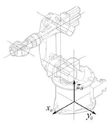
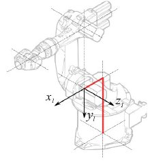
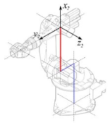
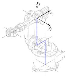
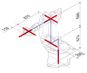
La descrizione è conforme alla Convenzione di Denavit-Hartenberg per i parametri, come descritto anche nel libro Introduction to Robotics di John J. Craigs.
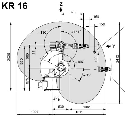
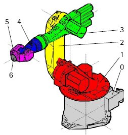
Esempio Kuka
|
|
|
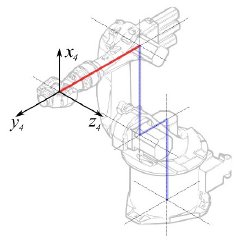
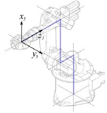
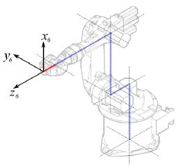
Cinematica
Questo porta alla seguente tabella:
| 1 | q1 | 675 mm | 260 mm | -90° |
| 2 | q2 - 90° | 0 mm | 680 mm | 0° |
| 3 | q3 | 0 mm | 0 mm | 90° |
| 4 | q4 | -670 mm | 0 mm | -90° |
| 5 | q5 | 0 mm | 0 mm | 90° |
| 6 | q6 | -158 mm | 0 mm | 180° |
Dato che i robot Kuka non hanno tutti gli assi a 0 nella posizione a L disegnata, si devono modificare gli assi 2 e 3 di 90 °.
| 1 | q1 | 675 mm | 260 mm | -90° |
| 2 | q2 | 0 mm | 680 mm | 0° |
| 3 | q3 - 90° | 0 mm | 0 mm | 90° |
| 4 | q4 | -670 mm | 0 mm | -90° |
| 5 | q5 | 0 mm | 0 mm | 90° |
| 6 | q6 | -158 mm | 0 mm | 180° |
Nella scheda tecnica si trovano ulteriori informazioni sugli assi:

Questo permette di compilare la tabella completa:
| Axis Speed | |||||||
|---|---|---|---|---|---|---|---|
| 1 | 0 | 675 | 260 | -90 | -185 | 185 | 156 |
| 2 | 0 | 0 | 680 | 0 | -155 | 35 | 156 |
| 3 | - 90 | 0 | 0 | 90 | -130 | 154 | 156 |
| 4 | 0 | -670 | 0 | -90 | -350 | 350 | 330 |
| 5 | 0 | 0 | 0 | 90 | -130 | 130 | 330 |
| 6 | 0 | -158 | 0 | 180 | -350 | 350 | 615 |
Rappresentazione visiva
FreeCAD can generate a rough visual out of the kinematic table. But if you want closer to reality you can use a VRML file with the robot shape for the simulation. E.g. Kuka delivers for its model VRML files. The VRML file gets loaded while the creation of the specific robot in FreeCAD. In order to allow FreeCAD to move the axis we have to edit the VRML file and insert special transformation nodes FreeCAD can find and manipulate.
Anche questo esempio si riferisce a un Kuka KR 16. Cominciando dalla riga 1:
#VRML V2.0 utf8
#
# This VRML97 file was exported using eM-Workplace
# (c) Tecnomatix Technologies GmbH & Co. KG
#     Heisenberg-Bogen 1
#     D-85609 Aschheim-Dornach
#     GERMANY
#
#Background
#{
#   skyColor   [0.752941 0.752941 0.752941]
#}
Transform
{
   #rotation 1 0 0 -1.5707963
   #scale .001 .001 .001
   children
   [
           DEF AOBJ_0001_000_TRAFO Transform
           {
              children
              [
...
Si vede che questo file è stato esportato con un software di simulazione di robot chiamato Tecnomatix. Rimuovere questa nota e inserire l'URL da cui si è ottenuto il file, perché Tecnomatix non ha nessun copyright sul contenuto del file. E' solo un convertitore! Iniziare con il rimuovere il nodo Background. Quindi rimuovere i nodi rotation e scale per ottenere il modello in mm e l'asse Z verticale.
Poi, proprio alla fine:
  ] }
  ] }
  ] }
  ]
}
#ROUTE SENS_04_OBJ.rotation_changed TO AXIS_04_OBJ.rotation
#ROUTE SENS_27_OBJ.rotation_changed TO AXIS_27_OBJ.rotation
#ROUTE SENS_32_OBJ.rotation_changed TO AXIS_32_OBJ.rotation
#ROUTE SENS_44_OBJ.rotation_changed TO AXIS_44_OBJ.rotation
#ROUTE SENS_46_OBJ.rotation_changed TO AXIS_46_OBJ.rotation
#ROUTE SENS_49_OBJ.rotation_changed TO AXIS_49_OBJ.rotation
#DEF AnySIMTimer TimeSensor
#{
#   cycleInterval 1.000000
#   loop          TRUE
#}
Togliere il segno di commento a TimeSensor e alle 6 rotte. Questo 6 righe indicano dove si trova l'asse effettivo del robot! Ricercare AXIS_04_OBJ e arrivare a questa parte del file:
...
    Transform { rotation 1 0 0 1.570796 children [
        DEF SENS_04_OBJ-0001 CylinderSensor
        {
           diskAngle 1.570796
           minAngle  -3.228859
           maxAngle  3.228859
           offset    0.000000
        }
      DEF FREECAD_AXIS1 Transform { rotation 0 1 0 0 children [
      DEF AXIS_04_OBJ-0001 Transform
     {
        children
        [
        Transform { rotation 1 0 0 -1.570796 children [
           DEF AOBJ_0001_003_TRAFO Transform
           {
              rotation 1.000000 0.000000 0.000000 3.141593
              translation -600.000000 500.000000 300.000000
              children
              [
...
You have to insert exactly above the definition of this node the line "DEF FREECAD_AXIS1 Transform { rotation 0 1 0 0 children [" which is the anchor for FreeCAD to move the axis.
Poi fare la stessa cosa per FREECAD_AXIS2,FREECAD_AXIS3,FREECAD_AXIS4,FREECAD_AXIS5 e FREECAD_AXIS6. Non dimenticare le parentesi di chiusura alla fine del file e il gioco è fatto!
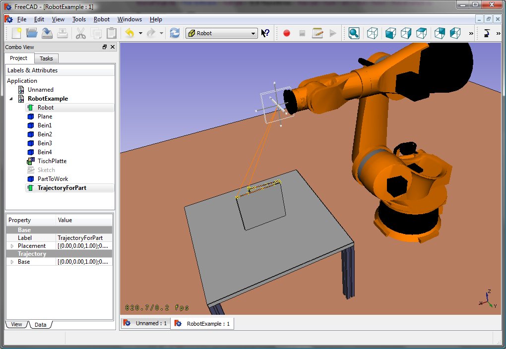
Ora è possibile caricare il file VRML per installare il robot con:
App.activeDocument().addObject("Robot::RobotObject","Robot")
App.activeDocument().Robot.RobotVrmlFile = "C:/_Projekte/FreeCAD0.9_build/mod/Robot/Lib/Kuka/kr16.wrl"
Che dovrebbe dare questo risultato:
KR 210
| Axis Speed | |||||||
|---|---|---|---|---|---|---|---|
| 1 | 0 | 750 | 350 | -90 | -185 | 185 | 156 |
| 2 | 0 | 0 | 1250 | 0 | -155 | 35 | 156 |
| 3 | - 90 | 0 | 0 | 90 | -130 | 154 | 156 |
| 4 | 0 | -1100 | 0 | -90 | -350 | 350 | 330 |
| 5 | 0 | 0 | 0 | 90 | -130 | 130 | 330 |
| 6 | 0 | -230 | 0 | 180 | -350 | 350 | 615 |
KR 500
| Axis Speed | |||||||
|---|---|---|---|---|---|---|---|
| 1 | 0 | 1045 | 500 | -90 | -185 | 185 | 156 |
| 2 | 0 | 0 | 1300 | 0 | -155 | 35 | 156 |
| 3 | - 90 | 0 | 0 | 90 | -130 | 154 | 156 |
| 4 | 0 | -1025 | 0 | -90 | -350 | 350 | 330 |
| 5 | 0 | 0 | 0 | 90 | -130 | 130 | 330 |
| 6 | 0 | -250 | 0 | 180 | -350 | 350 | 615 |
