Robot 6-Axis/it: Difference between revisions
Emagdalena (talk | contribs) (Created page with "Poi fare la stessa cosa per '''FREECAD_AXIS2''','''FREECAD_AXIS3''','''FREECAD_AXIS4''','''FREECAD_AXIS5''' e '''FREECAD_AXIS6'''. Non dimenticare le parentesi di chiusura all...") |
(Created page with "=== Collegamenti ===") |
||
| (32 intermediate revisions by 5 users not shown) | |||
| Line 1: | Line 1: | ||
| ⚫ | |||
Questo articolo descrive come importare in FreeCAD un robot industriale standard a 6 assi a scopo di simulazione. |
|||
{{TutorialInfo/it |
|||
|Topic= Robot |
|||
|Level= Intermedio |
|||
|Time= |
|||
|Author= |
|||
|FCVersion= |
|||
|Files= |
|||
}} |
|||
<span id="Overview"></span> |
|||
==Vista generale== |
|||
Questo articolo riguarda il portare un robot industriale standard a 6 assi in FreeCAD per la simulazione nel [[Image:Workbench_Robot.svg|24px]] [[Robot Workbench/it|Ambiente Robot]] |
|||
La descrizione è conforme alla [http://it.wikipedia.org/wiki/Convenzione_di_Denavit-Hartenberg Convenzione di Denavit-Hartenberg] per i parametri, come descritto anche nel libro '''Introduction to Robotics''' di John J. Craigs. |
La descrizione è conforme alla [http://it.wikipedia.org/wiki/Convenzione_di_Denavit-Hartenberg Convenzione di Denavit-Hartenberg] per i parametri, come descritto anche nel libro '''Introduction to Robotics''' di John J. Craigs. |
||
<span id="Example_Kuka"></span> |
|||
== Esempio Kuka == |
== Esempio Kuka == |
||
| Line 14: | Line 29: | ||
|} |
|} |
||
<span id="Kinematic"></span> |
|||
=== Cinematica === |
=== Cinematica === |
||
| Line 20: | Line 36: | ||
|- |
|- |
||
! Segmento |
! Segmento |
||
! Parametro |
|||
! Parametri |
|||
! Descrizione |
! Descrizione |
||
|- |
|- |
||
| Line 35: | Line 51: | ||
<math>a_{1} = 260 mm </math> |
<math>a_{1} = 260 mm </math> |
||
<math>\alpha_{1} = |
<math>\alpha_{1} = -90</math>° |
||
|| Segmento 1 |
|| Segmento 1 |
||
| Line 147: | Line 163: | ||
Nella scheda tecnica si trovano ulteriori informazioni sugli assi: |
Nella scheda tecnica si trovano ulteriori informazioni sugli assi: |
||
[[Image:KukaAxisData.jpg]] |
[[Image:KukaAxisData.jpg]] |
||
| Line 168: | Line 185: | ||
|} |
|} |
||
<span id="Visual_representation"></span> |
|||
=== Rappresentazione visiva === |
=== Rappresentazione visiva === |
||
FreeCAD può generare una soddisfacente rappresentazione visiva della tabella cinematica. Se si desidera una visione più vicina alla realtà è possibile utilizzare per la simulazione un file VRML con la forma del robot. Ad esempio, [http://kuka.com Kuka] offre dei file VRML per i suoi modelli. In FreeCAD il file VRML viene caricato durante la creazione di un robot specifico. Per consentire a FreeCAD di muovere gli assi, si deve editare il file VRML e inserire degli speciali nodi di trasformazione che FreeCAD possa trovare e manipolare. |
|||
FreeCAD can generate a rough visual out of the kinematic table. But if you want closer to reality you can use a VRML file with the robot shape for the simulation. |
|||
E.g. [http://kuka.com Kuka] delivers for its model VRML files. |
|||
The VRML file gets loaded while the creation of the specific robot in FreeCAD. In order to allow FreeCAD to move the axis we have to edit the VRML file and insert special transformation nodes FreeCAD can find and manipulate. |
|||
Anche questo esempio si riferisce a un Kuka KR 16. |
Anche questo esempio si riferisce a un Kuka KR 16. |
||
| Line 244: | Line 260: | ||
[ |
[ |
||
... |
... |
||
Dove si deve inserire immediatamente sopra la definizione di questo nodo la riga '''"DEF FREECAD_AXIS1 Transform { rotation 0 1 0 0 children ["''' che è l'ancora che FreeCAD utilizza per spostare questo asse. |
|||
Poi fare la stessa cosa per '''FREECAD_AXIS2''','''FREECAD_AXIS3''','''FREECAD_AXIS4''','''FREECAD_AXIS5''' e '''FREECAD_AXIS6'''. Non dimenticare le parentesi di chiusura alla fine del file e il gioco è fatto! |
Poi fare la stessa cosa per '''FREECAD_AXIS2''','''FREECAD_AXIS3''','''FREECAD_AXIS4''','''FREECAD_AXIS5''' e '''FREECAD_AXIS6'''. Non dimenticare le parentesi di chiusura alla fine del file e il gioco è fatto! |
||
Ora è possibile caricare il file VRML per installare il robot con: |
|||
App.activeDocument().addObject("Robot::RobotObject","Robot") |
App.activeDocument().addObject("Robot::RobotObject","Robot") |
||
App.activeDocument().Robot.RobotVrmlFile = "C:/_Projekte/FreeCAD0.9_build/mod/Robot/Lib/Kuka/kr16.wrl" |
App.activeDocument().Robot.RobotVrmlFile = "C:/_Projekte/FreeCAD0.9_build/mod/Robot/Lib/Kuka/kr16.wrl" |
||
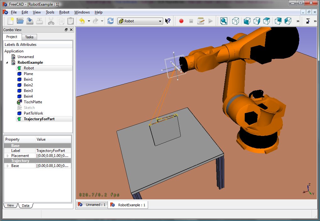
Che dovrebbe dare questo risultato: |
|||
which should give you that result: |
|||
[[Image:KukaKR16FreeCAD.jpg]] |
[[Image:KukaKR16FreeCAD.jpg]] |
||
| Line 259: | Line 275: | ||
{| class="wikitable" style="color:green; background-color:#ffffcc;" cellpadding="5" cellspacing="0" border="1" |
{| class="wikitable" style="color:green; background-color:#ffffcc;" cellpadding="5" cellspacing="0" border="1" |
||
|+ ''' |
|+ '''Tabella cinematica''' |
||
|- |
|- |
||
! <math>i</math> !! <math>\theta</math> !! <math>d</math> !! <math>a</math> !! <math>\alpha</math> !! <math>\theta_{min}</math> !! <math>\theta_{max}</math> !! Axis Speed |
! <math>i</math> !! <math>\theta</math> !! <math>d</math> !! <math>a</math> !! <math>\alpha</math> !! <math>\theta_{min}</math> !! <math>\theta_{max}</math> !! Axis Speed |
||
| Line 282: | Line 298: | ||
{| class="wikitable" style="color:green; background-color:#ffffcc;" cellpadding="5" cellspacing="0" border="1" |
{| class="wikitable" style="color:green; background-color:#ffffcc;" cellpadding="5" cellspacing="0" border="1" |
||
|+ ''' |
|+ '''Tabella cinematica''' |
||
|- |
|- |
||
! <math>i</math> !! <math>\theta</math> !! <math>d</math> !! <math>a</math> !! <math>\alpha</math> !! <math>\theta_{min}</math> !! <math>\theta_{max}</math> !! Axis Speed |
! <math>i</math> !! <math>\theta</math> !! <math>d</math> !! <math>a</math> !! <math>\alpha</math> !! <math>\theta_{min}</math> !! <math>\theta_{max}</math> !! Axis Speed |
||
| Line 299: | Line 315: | ||
|} |
|} |
||
<span id="Links"></span> |
|||
[[Category:User Documentation]] |
|||
=== Collegamenti === |
|||
| ⚫ | |||
* [https://link.springer.com/referenceworkentry/10.1007%2F978-3-540-30301-5_2 Springer Handbook of Robotics, section Kinematics, p 9-33]. |
|||
* [https://www.youtube.com/watch?v=qZB3_gKBwf8 Denavit-Hartenberg Parameter 3D Video Tutorial] Denavit-Hartenberg Parameter 3D Video Tutorial for a KUKA industry robot on YouTube (german). |
|||
* [https://www.youtube.com/watch?v=rA9tm0gTln8 Denavit-Hartenberg Reference Frame Layout] Denavit-Hartenberg Reference Frame Layout on YouTube. |
|||
* [http://www.roboanalyzer.com/ RoboAnalyzer] RoboAnalyzer is a 3D model based software that can be used to teach and learn the Robotics concepts. |
|||
{{Robot_Tools_navi{{#translation:}}}} |
|||
{{Userdocnavi{{#translation:}}}} |
|||
Latest revision as of 20:22, 12 April 2024
| Argomento |
|---|
| Robot |
| Livello di difficoltà |
| Intermedio |
| Tempo di esecuzione |
| Autori |
| Versione di FreeCAD |
| Files di esempio |
| Vedere anche |
| Nessuno |
Vista generale
Questo articolo riguarda il portare un robot industriale standard a 6 assi in FreeCAD per la simulazione nel Ambiente Robot
La descrizione è conforme alla Convenzione di Denavit-Hartenberg per i parametri, come descritto anche nel libro Introduction to Robotics di John J. Craigs.
Esempio Kuka
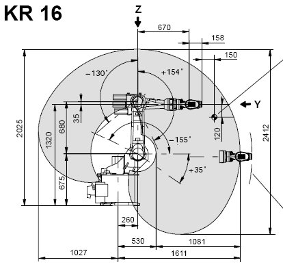
|
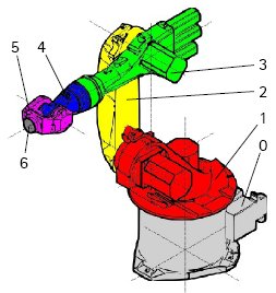
|
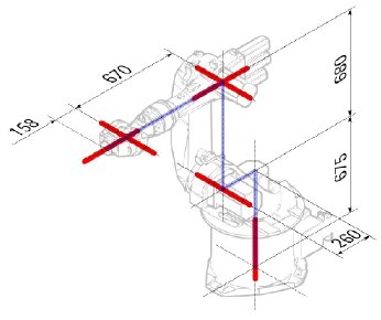
|
Cinematica
| Segmento | Parametro | Descrizione |
|---|---|---|
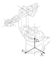
|
Configurazione di base | |
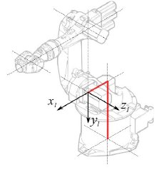
|
° |
Segmento 1 |
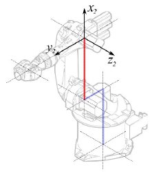
|
°
° |
Segmento 2 |
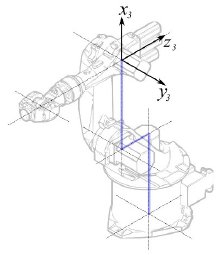
|
° |
Segmento 3 |
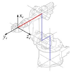
|
° |
Segmento 4 |
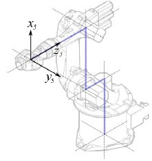
|
° |
Segmento 5 |
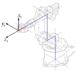
|
° |
Segmento 6 |
Questo porta alla seguente tabella:
| 1 | q1 | 675 mm | 260 mm | -90° |
| 2 | q2 - 90° | 0 mm | 680 mm | 0° |
| 3 | q3 | 0 mm | 0 mm | 90° |
| 4 | q4 | -670 mm | 0 mm | -90° |
| 5 | q5 | 0 mm | 0 mm | 90° |
| 6 | q6 | -158 mm | 0 mm | 180° |
Dato che i robot Kuka non hanno tutti gli assi a 0 nella posizione a L disegnata, si devono modificare gli assi 2 e 3 di 90 °.
| 1 | q1 | 675 mm | 260 mm | -90° |
| 2 | q2 | 0 mm | 680 mm | 0° |
| 3 | q3 - 90° | 0 mm | 0 mm | 90° |
| 4 | q4 | -670 mm | 0 mm | -90° |
| 5 | q5 | 0 mm | 0 mm | 90° |
| 6 | q6 | -158 mm | 0 mm | 180° |
Nella scheda tecnica si trovano ulteriori informazioni sugli assi:
Questo permette di compilare la tabella completa:
| Axis Speed | |||||||
|---|---|---|---|---|---|---|---|
| 1 | 0 | 675 | 260 | -90 | -185 | 185 | 156 |
| 2 | 0 | 0 | 680 | 0 | -155 | 35 | 156 |
| 3 | - 90 | 0 | 0 | 90 | -130 | 154 | 156 |
| 4 | 0 | -670 | 0 | -90 | -350 | 350 | 330 |
| 5 | 0 | 0 | 0 | 90 | -130 | 130 | 330 |
| 6 | 0 | -158 | 0 | 180 | -350 | 350 | 615 |
Rappresentazione visiva
FreeCAD può generare una soddisfacente rappresentazione visiva della tabella cinematica. Se si desidera una visione più vicina alla realtà è possibile utilizzare per la simulazione un file VRML con la forma del robot. Ad esempio, Kuka offre dei file VRML per i suoi modelli. In FreeCAD il file VRML viene caricato durante la creazione di un robot specifico. Per consentire a FreeCAD di muovere gli assi, si deve editare il file VRML e inserire degli speciali nodi di trasformazione che FreeCAD possa trovare e manipolare.
Anche questo esempio si riferisce a un Kuka KR 16. Cominciando dalla riga 1:
#VRML V2.0 utf8
#
# This VRML97 file was exported using eM-Workplace
# (c) Tecnomatix Technologies GmbH & Co. KG
#     Heisenberg-Bogen 1
#     D-85609 Aschheim-Dornach
#     GERMANY
#
#Background
#{
#   skyColor   [0.752941 0.752941 0.752941]
#}
Transform
{
   #rotation 1 0 0 -1.5707963
   #scale .001 .001 .001
   children
   [
           DEF AOBJ_0001_000_TRAFO Transform
           {
              children
              [
...
Si vede che questo file è stato esportato con un software di simulazione di robot chiamato Tecnomatix. Rimuovere questa nota e inserire l'URL da cui si è ottenuto il file, perché Tecnomatix non ha nessun copyright sul contenuto del file. E' solo un convertitore! Iniziare con il rimuovere il nodo Background. Quindi rimuovere i nodi rotation e scale per ottenere il modello in mm e l'asse Z verticale.
Poi, proprio alla fine:
  ] }
  ] }
  ] }
  ]
}
#ROUTE SENS_04_OBJ.rotation_changed TO AXIS_04_OBJ.rotation
#ROUTE SENS_27_OBJ.rotation_changed TO AXIS_27_OBJ.rotation
#ROUTE SENS_32_OBJ.rotation_changed TO AXIS_32_OBJ.rotation
#ROUTE SENS_44_OBJ.rotation_changed TO AXIS_44_OBJ.rotation
#ROUTE SENS_46_OBJ.rotation_changed TO AXIS_46_OBJ.rotation
#ROUTE SENS_49_OBJ.rotation_changed TO AXIS_49_OBJ.rotation
#DEF AnySIMTimer TimeSensor
#{
#   cycleInterval 1.000000
#   loop          TRUE
#}
Togliere il segno di commento a TimeSensor e alle 6 rotte. Questo 6 righe indicano dove si trova l'asse effettivo del robot! Ricercare AXIS_04_OBJ e arrivare a questa parte del file:
...
    Transform { rotation 1 0 0 1.570796 children [
        DEF SENS_04_OBJ-0001 CylinderSensor
        {
           diskAngle 1.570796
           minAngle  -3.228859
           maxAngle  3.228859
           offset    0.000000
        }
      DEF FREECAD_AXIS1 Transform { rotation 0 1 0 0 children [
      DEF AXIS_04_OBJ-0001 Transform
     {
        children
        [
        Transform { rotation 1 0 0 -1.570796 children [
           DEF AOBJ_0001_003_TRAFO Transform
           {
              rotation 1.000000 0.000000 0.000000 3.141593
              translation -600.000000 500.000000 300.000000
              children
              [
...
Dove si deve inserire immediatamente sopra la definizione di questo nodo la riga "DEF FREECAD_AXIS1 Transform { rotation 0 1 0 0 children [" che è l'ancora che FreeCAD utilizza per spostare questo asse.
Poi fare la stessa cosa per FREECAD_AXIS2,FREECAD_AXIS3,FREECAD_AXIS4,FREECAD_AXIS5 e FREECAD_AXIS6. Non dimenticare le parentesi di chiusura alla fine del file e il gioco è fatto!
Ora è possibile caricare il file VRML per installare il robot con:
App.activeDocument().addObject("Robot::RobotObject","Robot")
App.activeDocument().Robot.RobotVrmlFile = "C:/_Projekte/FreeCAD0.9_build/mod/Robot/Lib/Kuka/kr16.wrl"
Che dovrebbe dare questo risultato:
KR 210
| Axis Speed | |||||||
|---|---|---|---|---|---|---|---|
| 1 | 0 | 750 | 350 | -90 | -185 | 185 | 156 |
| 2 | 0 | 0 | 1250 | 0 | -155 | 35 | 156 |
| 3 | - 90 | 0 | 0 | 90 | -130 | 154 | 156 |
| 4 | 0 | -1100 | 0 | -90 | -350 | 350 | 330 |
| 5 | 0 | 0 | 0 | 90 | -130 | 130 | 330 |
| 6 | 0 | -230 | 0 | 180 | -350 | 350 | 615 |
KR 500
| Axis Speed | |||||||
|---|---|---|---|---|---|---|---|
| 1 | 0 | 1045 | 500 | -90 | -185 | 185 | 156 |
| 2 | 0 | 0 | 1300 | 0 | -155 | 35 | 156 |
| 3 | - 90 | 0 | 0 | 90 | -130 | 154 | 156 |
| 4 | 0 | -1025 | 0 | -90 | -350 | 350 | 330 |
| 5 | 0 | 0 | 0 | 90 | -130 | 130 | 330 |
| 6 | 0 | -250 | 0 | 180 | -350 | 350 | 615 |
Collegamenti
- Springer Handbook of Robotics, section Kinematics, p 9-33.
- Denavit-Hartenberg Parameter 3D Video Tutorial Denavit-Hartenberg Parameter 3D Video Tutorial for a KUKA industry robot on YouTube (german).
- Denavit-Hartenberg Reference Frame Layout Denavit-Hartenberg Reference Frame Layout on YouTube.
- RoboAnalyzer RoboAnalyzer is a 3D model based software that can be used to teach and learn the Robotics concepts.
- Trajectories, non parametric: Create a trajectory, Set default orientation, Set default values, Insert waypoint, Insert waypoint (mouse)
- Trajectories, parametric: Create a trajectory from edges, Dress-up trajectory, Trajectory compound
- Getting started
- Installation: Download, Windows, Linux, Mac, Additional components, Docker, AppImage, Ubuntu Snap
- Basics: About FreeCAD, Interface, Mouse navigation, Selection methods, Object name, Preferences, Workbenches, Document structure, Properties, Help FreeCAD, Donate
- Help: Tutorials, Video tutorials
- Workbenches: Std Base, Arch, Assembly, CAM, Draft, FEM, Inspection, Mesh, OpenSCAD, Part, PartDesign, Points, Reverse Engineering, Robot, Sketcher, Spreadsheet, Surface, TechDraw, Test Framework
- Hubs: User hub, Power users hub, Developer hub


