6-ti osový robot
Tento článek je o zavedení standardů 6-ti osového průmyslového robota pro simulaci ve FreeCADu.
popis vychází ze systému Denavit-Hartenberg Parameter, podobně jak popisuje John J. Craigs v knize "Introduction to Robotics".
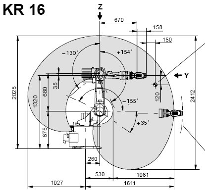
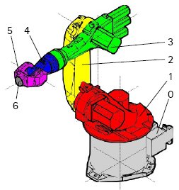
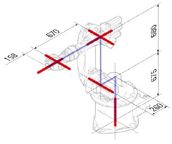
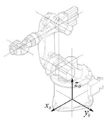
Příklad Kuka
|
|
|
Kinematika
| Segment | Parameter | Popis |
|---|---|---|
|
Základní konfigurace | |
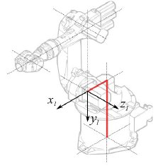
|
Failed to parse (syntax error): {\displaystyle \alpha_{1} = −90} ° |
Segment 1 |
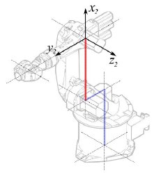
|
°
° |
Segment 2 |
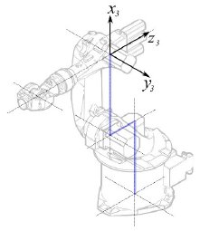
|
° |
Segment 3 |
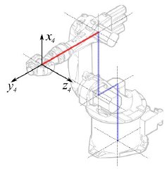
|
° |
Segment 4 |
|
° |
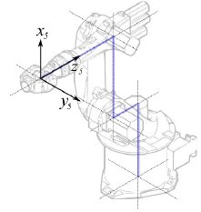
Segment 5 |
|
° |
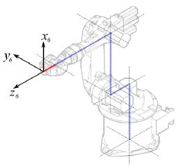
Segment 6 |
Řídí se následující tabulkou:
| 1 | q1 | 675 mm | 260 mm | -90° |
| 2 | q2 - 90° | 0 mm | 680 mm | 0° |
| 3 | q3 | 0 mm | 0 mm | 90° |
| 4 | q4 | -670 mm | 0 mm | -90° |
| 5 | q5 | 0 mm | 0 mm | 90° |
| 6 | q6 | -158 mm | 0 mm | 180° |
Protože roboty Kuka nemají všechny osy do 0 v nakreslené L-pozici, musíme změnit osy 2 a 3 o 90°.
| 1 | q1 | 675 mm | 260 mm | -90° |
| 2 | q2 | 0 mm | 680 mm | 0° |
| 3 | q3 - 90° | 0 mm | 0 mm | 90° |
| 4 | q4 | -670 mm | 0 mm | -90° |
| 5 | q5 | 0 mm | 0 mm | 90° |
| 6 | q6 | -158 mm | 0 mm | 180° |
V popisu robota jsou navíc i informace o ose:

Výsledkem je kompletní tabulka:
| Axis Speed | |||||||
|---|---|---|---|---|---|---|---|
| 1 | 0 | 675 | 260 | -90 | -185 | 185 | 156 |
| 2 | 0 | 0 | 680 | 0 | -155 | 35 | 156 |
| 3 | - 90 | 0 | 0 | 90 | -130 | 154 | 156 |
| 4 | 0 | -670 | 0 | -90 | -350 | 350 | 330 |
| 5 | 0 | 0 | 0 | 90 | -130 | 130 | 330 |
| 6 | 0 | -158 | 0 | 180 | -350 | 350 | 615 |
Vizuální reprezentace
FreeCAD může generovat neupravený vizuální výstup kinematické taulky. Ale pokud se chcete dostat blíž k realitě, můžete pro simulaci použít VRML soubor s tvary robota. Např. dodávané Kuka soubory pro jejich model. Při vytváření specifického robota ve FreeCADu je natahován soubor VRML. Pokud je FreeCADu umožněno posunovat osy, musí být upraven VRML soubor a vloženy speciální transformační uzly, které FreeCAD může nalézt a manipulovat s nimi.
Ještě jednou ukážeme příklad Kuka KR 16. Začínáme od řádku 1:
#VRML V2.0 utf8
#
# This VRML97 file was exported using eM-Workplace
# (c) Tecnomatix Technologies GmbH & Co. KG
#     Heisenberg-Bogen 1
#     D-85609 Aschheim-Dornach
#     GERMANY
#
#Background
#{
#   skyColor   [0.752941 0.752941 0.752941]
#}
Transform
{
   #rotation 1 0 0 -1.5707963
   #scale .001 .001 .001
   children
   [
           DEF AOBJ_0001_000_TRAFO Transform
           {
              children
              [
...
You see this file is exported with a robot simulation software called Tecnomatix. Remove this notice and put in a URL where you get this file from, because Tecnomatix has no copyright in the file content. It's only a converter! First of all we remove the Background node. Then remove the rotation and scale node to get the model to mm and upright Z.
Right at the end:
  ] }
  ] }
  ] }
  ]
}
#ROUTE SENS_04_OBJ.rotation_changed TO AXIS_04_OBJ.rotation
#ROUTE SENS_27_OBJ.rotation_changed TO AXIS_27_OBJ.rotation
#ROUTE SENS_32_OBJ.rotation_changed TO AXIS_32_OBJ.rotation
#ROUTE SENS_44_OBJ.rotation_changed TO AXIS_44_OBJ.rotation
#ROUTE SENS_46_OBJ.rotation_changed TO AXIS_46_OBJ.rotation
#ROUTE SENS_49_OBJ.rotation_changed TO AXIS_49_OBJ.rotation
#DEF AnySIMTimer TimeSensor
#{
#   cycleInterval 1.000000
#   loop          TRUE
#}
Comment out the TimeSensor and the 6 routes. This 6 lines give you a hint where the actual axis of the robot are! First search for "AXIS_04_OBJ" that brings you to that place:
...
    Transform { rotation 1 0 0 1.570796 children [
        DEF SENS_04_OBJ-0001 CylinderSensor
        {
           diskAngle 1.570796
           minAngle  -3.228859
           maxAngle  3.228859
           offset    0.000000
        }
      DEF FREECAD_AXIS1 Transform { rotation 0 1 0 0 children [
      DEF AXIS_04_OBJ-0001 Transform
     {
        children
        [
        Transform { rotation 1 0 0 -1.570796 children [
           DEF AOBJ_0001_003_TRAFO Transform
           {
              rotation 1.000000 0.000000 0.000000 3.141593
              translation -600.000000 500.000000 300.000000
              children
              [
...
You have to insert exactly above the definition of this node the line "DEF FREECAD_AXIS1 Transform { rotation 0 1 0 0 children [" which is the anchor for FreeCAD to move the axis.
Now do the same for FREECAD_AXIS2,FREECAD_AXIS3,FREECAD_AXIS4,FREECAD_AXIS5 and FREECAD_AXIS6. Don't forget the closing brackets at the end of the file and you're done!
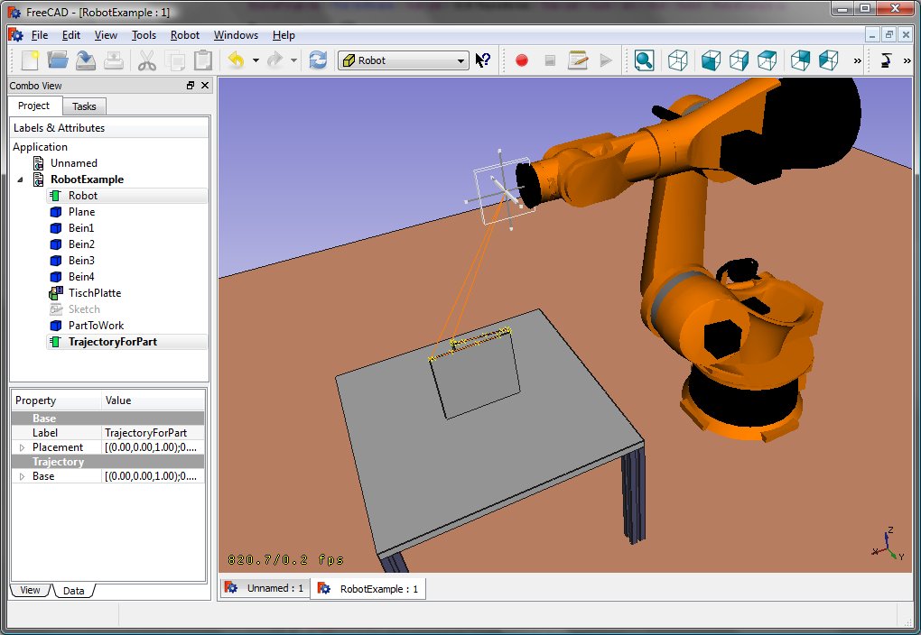
You can load the VRML by instantiating the robot:
App.activeDocument().addObject("Robot::RobotObject","Robot")
App.activeDocument().Robot.RobotVrmlFile = "C:/_Projekte/FreeCAD0.9_build/mod/Robot/Lib/Kuka/kr16.wrl"
which should give you that result:
KR 210
| Axis Speed | |||||||
|---|---|---|---|---|---|---|---|
| 1 | 0 | 750 | 350 | -90 | -185 | 185 | 156 |
| 2 | 0 | 0 | 1250 | 0 | -155 | 35 | 156 |
| 3 | - 90 | 0 | 0 | 90 | -130 | 154 | 156 |
| 4 | 0 | -1100 | 0 | -90 | -350 | 350 | 330 |
| 5 | 0 | 0 | 0 | 90 | -130 | 130 | 330 |
| 6 | 0 | -230 | 0 | 180 | -350 | 350 | 615 |
KR 500
| Axis Speed | |||||||
|---|---|---|---|---|---|---|---|
| 1 | 0 | 1045 | 500 | -90 | -185 | 185 | 156 |
| 2 | 0 | 0 | 1300 | 0 | -155 | 35 | 156 |
| 3 | - 90 | 0 | 0 | 90 | -130 | 154 | 156 |
| 4 | 0 | -1025 | 0 | -90 | -350 | 350 | 330 |
| 5 | 0 | 0 | 0 | 90 | -130 | 130 | 330 |
| 6 | 0 | -250 | 0 | 180 | -350 | 350 | 615 |


