Robot 6-Axis/cs: Difference between revisions
(Created page with "V popisu robota jsou navíc i informace o ose:") |
(Updating to match new version of source page) |
||
| (29 intermediate revisions by 3 users not shown) | |||
| Line 1: | Line 1: | ||
| ⚫ | |||
{{TutorialInfo/cs |
|||
|Topic= Robot Workbench |
|||
|Level= Intermediate |
|||
|Time= Unknown |
|||
|Author= |
|||
|FCVersion= |
|||
|Files= |
|||
}} |
|||
==Overview== |
|||
<div class="mw-translate-fuzzy"> |
|||
Tento článek je o zavedení standardů 6-ti osového průmyslového robota pro simulaci ve FreeCADu. |
Tento článek je o zavedení standardů 6-ti osového průmyslového robota pro simulaci ve FreeCADu. |
||
</div> |
|||
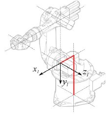
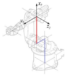
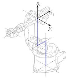
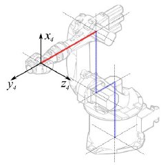
Popis vychází ze systému [http://en.wikipedia.org/wiki/Denavit-Hartenberg_Parameters Denavit-Hartenberg Parameter], podobně jak popisuje John J. Craigs v knize "Introduction to Robotics". |
|||
<span id="Example_Kuka"></span> |
|||
== Příklad Kuka == |
== Příklad Kuka == |
||
| Line 14: | Line 30: | ||
|} |
|} |
||
<span id="Kinematic"></span> |
|||
=== Kinematika === |
=== Kinematika === |
||
| Line 35: | Line 52: | ||
<math>a_{1} = 260 mm </math> |
<math>a_{1} = 260 mm </math> |
||
<math>\alpha_{1} = |
<math>\alpha_{1} = -90</math>° |
||
|| Segment 1 |
|| Segment 1 |
||
| Line 108: | Line 125: | ||
{| class="wikitable" style="color:green; background-color:#ffffcc;" cellpadding="5" cellspacing="0" border="1" |
{| class="wikitable" style="color:green; background-color:#ffffcc;" cellpadding="5" cellspacing="0" border="1" |
||
|+ <div class="mw-translate-fuzzy"> |
|||
'''Kinematická tabulka''' |
|||
</div> |
|||
|- |
|- |
||
! <math>i</math> !! <math>\theta</math> !! <math>d</math> !! <math>a</math> !! <math>\alpha</math> |
! <math>i</math> !! <math>\theta</math> !! <math>d</math> !! <math>a</math> !! <math>\alpha</math> |
||
| Line 129: | Line 148: | ||
{| class="wikitable" style="color:green; background-color:#ffffcc;" cellpadding="5" cellspacing="0" border="1" |
{| class="wikitable" style="color:green; background-color:#ffffcc;" cellpadding="5" cellspacing="0" border="1" |
||
|+ <div class="mw-translate-fuzzy"> |
|||
'''Kinematická tabulka''' |
|||
</div> |
|||
|- |
|- |
||
! <math>i</math> !! <math>\theta</math> !! <math>d</math> !! <math>a</math> !! <math>\alpha</math> |
! <math>i</math> !! <math>\theta</math> !! <math>d</math> !! <math>a</math> !! <math>\alpha</math> |
||
| Line 147: | Line 168: | ||
V popisu robota jsou navíc i informace o ose: |
V popisu robota jsou navíc i informace o ose: |
||
[[Image:KukaAxisData.jpg]] |
[[Image:KukaAxisData.jpg]] |
||
Výsledkem je kompletní tabulka: |
|||
That leads to this complete table: |
|||
{| class="wikitable" style="color:green; background-color:#ffffcc;" cellpadding="5" cellspacing="0" border="1" |
{| class="wikitable" style="color:green; background-color:#ffffcc;" cellpadding="5" cellspacing="0" border="1" |
||
|+ <div class="mw-translate-fuzzy"> |
|||
|+ '''Kinematik table''' |
|||
'''Kinematická tabulka''' |
|||
</div> |
|||
|- |
|- |
||
! <math>i</math> !! <math>\theta</math> !! <math>d</math> !! <math>a</math> !! <math>\alpha</math> !! <math>\theta_{min}</math> !! <math>\theta_{max}</math> !! Axis Speed |
! <math>i</math> !! <math>\theta</math> !! <math>d</math> !! <math>a</math> !! <math>\alpha</math> !! <math>\theta_{min}</math> !! <math>\theta_{max}</math> !! Axis Speed |
||
| Line 168: | Line 192: | ||
|} |
|} |
||
<span id="Visual_representation"></span> |
|||
=== Visual representation === |
|||
=== Vizuální reprezentace === |
|||
FreeCAD může generovat neupravený vizuální výstup kinematické taulky. Ale pokud se chcete dostat blíž k realitě, můžete pro simulaci použít VRML soubor s tvary robota. |
|||
FreeCAD can generate a rough visual out of the kinematic table. But if you want closer to reality you can use a VRML file with the robot shape for the simulation. |
|||
Např. dodávané [http://kuka.com Kuka] soubory pro jejich model. Při vytváření specifického robota ve FreeCADu je natahován soubor VRML. Pokud je FreeCADu umožněno posunovat osy, musí být upraven VRML soubor a vloženy speciální transformační uzly, které FreeCAD může nalézt a manipulovat s nimi. |
|||
E.g. [http://kuka.com Kuka] delivers for its model VRML files. |
|||
The VRML file gets loaded while the creation of the specific robot in FreeCAD. In order to allow FreeCAD to move the axis we have to edit the VRML file and insert special transformation nodes FreeCAD can find and manipulate. |
|||
Ještě jednou ukážeme příklad Kuka KR 16. |
|||
Začínáme od řádku 1: |
|||
Beginning from line 1: |
|||
#VRML V2.0 utf8 |
#VRML V2.0 utf8 |
||
| Line 200: | Line 224: | ||
[ |
[ |
||
... |
... |
||
Vidíte, že tento soubor je dodáván se simulačním software robota zvaným Tecnomatix. Odstraňte poznámku a vložte tam URL, ze které jste tento soubor získali, protože Tecnomatix nemá žádný copyright na obsah souboru. Je to pouze konvertor! Nejdřív odstraňte uzel '''Background'''. Potom odstraňte uzly '''rotation''' a '''scale''' abyste dostali model v mm a kolmou Z. |
|||
A teď na konci: |
|||
Right at the end: |
|||
] } |
] } |
||
] } |
] } |
||
| Line 220: | Line 244: | ||
#} |
#} |
||
Odkomentujte '''TimeSensor''' a 6 routes. Těch 6 řádků určuje kde jsou aktuální osy robota! Nejdříve se podívejte po "AXIS_04_OBJ" což Vás přivede na následující místo: |
|||
... |
... |
||
Transform { rotation 1 0 0 1.570796 children [ |
Transform { rotation 1 0 0 1.570796 children [ |
||
| Line 243: | Line 267: | ||
[ |
[ |
||
... |
... |
||
Přesně nad definici tohoto uzlu musíte vložit řádek '''"DEF FREECAD_AXIS1 Transform { rotation 0 1 0 0 children ["''' což je odkaz pro FreeCAD aby se přesunul na osy. |
|||
A teď to samé pro '''FREECAD_AXIS2''','''FREECAD_AXIS3''','''FREECAD_AXIS4''','''FREECAD_AXIS5''' a '''FREECAD_AXIS6'''. |
|||
Nezapomeňte na uzavírací závorky na konci souboru a pak jste hotovi! |
|||
Don't forget the closing brackets at the end of the file and you're done! |
|||
Při konkretizaci robota můžete natáhnout VRML: |
|||
You can load the VRML by instantiating the robot: |
|||
App.activeDocument().addObject("Robot::RobotObject","Robot") |
App.activeDocument().addObject("Robot::RobotObject","Robot") |
||
App.activeDocument().Robot.RobotVrmlFile = "C:/_Projekte/FreeCAD0.9_build/mod/Robot/Lib/Kuka/kr16.wrl" |
App.activeDocument().Robot.RobotVrmlFile = "C:/_Projekte/FreeCAD0.9_build/mod/Robot/Lib/Kuka/kr16.wrl" |
||
což by mělo dát tento výsledek: |
|||
which should give you that result: |
|||
[[Image:KukaKR16FreeCAD.jpg]] |
[[Image:KukaKR16FreeCAD.jpg]] |
||
| Line 259: | Line 283: | ||
{| class="wikitable" style="color:green; background-color:#ffffcc;" cellpadding="5" cellspacing="0" border="1" |
{| class="wikitable" style="color:green; background-color:#ffffcc;" cellpadding="5" cellspacing="0" border="1" |
||
|+ <div class="mw-translate-fuzzy"> |
|||
|+ '''Kinematik table''' |
|||
'''Kinematická tabulka''' |
|||
</div> |
|||
|- |
|- |
||
! <math>i</math> !! <math>\theta</math> !! <math>d</math> !! <math>a</math> !! <math>\alpha</math> !! <math>\theta_{min}</math> !! <math>\theta_{max}</math> !! Axis Speed |
! <math>i</math> !! <math>\theta</math> !! <math>d</math> !! <math>a</math> !! <math>\alpha</math> !! <math>\theta_{min}</math> !! <math>\theta_{max}</math> !! Axis Speed |
||
| Line 282: | Line 308: | ||
{| class="wikitable" style="color:green; background-color:#ffffcc;" cellpadding="5" cellspacing="0" border="1" |
{| class="wikitable" style="color:green; background-color:#ffffcc;" cellpadding="5" cellspacing="0" border="1" |
||
|+ <div class="mw-translate-fuzzy"> |
|||
|+ '''Kinematik table''' |
|||
'''Kinematická tabulka''' |
|||
</div> |
|||
|- |
|- |
||
! <math>i</math> !! <math>\theta</math> !! <math>d</math> !! <math>a</math> !! <math>\alpha</math> !! <math>\theta_{min}</math> !! <math>\theta_{max}</math> !! Axis Speed |
! <math>i</math> !! <math>\theta</math> !! <math>d</math> !! <math>a</math> !! <math>\alpha</math> !! <math>\theta_{min}</math> !! <math>\theta_{max}</math> !! Axis Speed |
||
| Line 299: | Line 327: | ||
|} |
|} |
||
=== Links === |
|||
[[Category:User Documentation]] |
|||
| ⚫ | |||
* [https://link.springer.com/referenceworkentry/10.1007%2F978-3-540-30301-5_2 Springer Handbook of Robotics, section Kinematics, p 9-33]. |
|||
* [https://www.youtube.com/watch?v=qZB3_gKBwf8 Denavit-Hartenberg Parameter 3D Video Tutorial] Denavit-Hartenberg Parameter 3D Video Tutorial for a KUKA industry robot on YouTube (german). |
|||
* [https://www.youtube.com/watch?v=rA9tm0gTln8 Denavit-Hartenberg Reference Frame Layout] Denavit-Hartenberg Reference Frame Layout on YouTube. |
|||
* [http://www.roboanalyzer.com/ RoboAnalyzer] RoboAnalyzer is a 3D model based software that can be used to teach and learn the Robotics concepts. |
|||
{{Robot_Tools_navi{{#translation:}}}} |
|||
{{Userdocnavi{{#translation:}}}} |
|||
Latest revision as of 12:56, 14 April 2023
| Topic |
|---|
| Robot Workbench |
| Level |
| Intermediate |
| Time to complete |
| Unknown |
| Authors |
| FreeCAD version |
| Example files |
| See also |
| None |
Overview
Tento článek je o zavedení standardů 6-ti osového průmyslového robota pro simulaci ve FreeCADu.
Popis vychází ze systému Denavit-Hartenberg Parameter, podobně jak popisuje John J. Craigs v knize "Introduction to Robotics".
Příklad Kuka
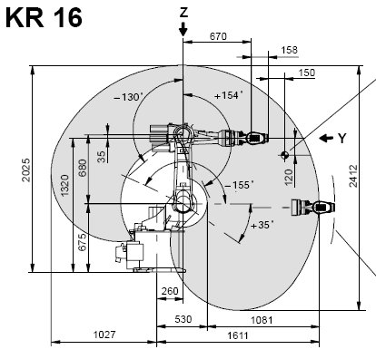
|
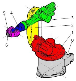
|
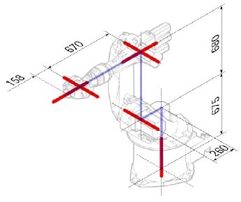
|
Kinematika
| Segment | Parameter | Popis |
|---|---|---|
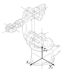
|
Základní konfigurace | |
|
° |
Segment 1 |
|
°
° |
Segment 2 |
|
° |
Segment 3 |
|
° |
Segment 4 |
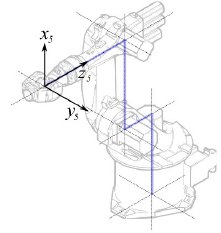
|
° |
Segment 5 |
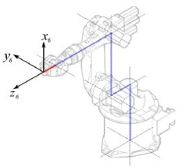
|
° |
Segment 6 |
Řídí se následující tabulkou:
| 1 | q1 | 675 mm | 260 mm | -90° |
| 2 | q2 - 90° | 0 mm | 680 mm | 0° |
| 3 | q3 | 0 mm | 0 mm | 90° |
| 4 | q4 | -670 mm | 0 mm | -90° |
| 5 | q5 | 0 mm | 0 mm | 90° |
| 6 | q6 | -158 mm | 0 mm | 180° |
Protože roboty Kuka nemají všechny osy do 0 v nakreslené L-pozici, musíme změnit osy 2 a 3 o 90°.
| 1 | q1 | 675 mm | 260 mm | -90° |
| 2 | q2 | 0 mm | 680 mm | 0° |
| 3 | q3 - 90° | 0 mm | 0 mm | 90° |
| 4 | q4 | -670 mm | 0 mm | -90° |
| 5 | q5 | 0 mm | 0 mm | 90° |
| 6 | q6 | -158 mm | 0 mm | 180° |
V popisu robota jsou navíc i informace o ose:
Výsledkem je kompletní tabulka:
| Axis Speed | |||||||
|---|---|---|---|---|---|---|---|
| 1 | 0 | 675 | 260 | -90 | -185 | 185 | 156 |
| 2 | 0 | 0 | 680 | 0 | -155 | 35 | 156 |
| 3 | - 90 | 0 | 0 | 90 | -130 | 154 | 156 |
| 4 | 0 | -670 | 0 | -90 | -350 | 350 | 330 |
| 5 | 0 | 0 | 0 | 90 | -130 | 130 | 330 |
| 6 | 0 | -158 | 0 | 180 | -350 | 350 | 615 |
Vizuální reprezentace
FreeCAD může generovat neupravený vizuální výstup kinematické taulky. Ale pokud se chcete dostat blíž k realitě, můžete pro simulaci použít VRML soubor s tvary robota. Např. dodávané Kuka soubory pro jejich model. Při vytváření specifického robota ve FreeCADu je natahován soubor VRML. Pokud je FreeCADu umožněno posunovat osy, musí být upraven VRML soubor a vloženy speciální transformační uzly, které FreeCAD může nalézt a manipulovat s nimi.
Ještě jednou ukážeme příklad Kuka KR 16. Začínáme od řádku 1:
#VRML V2.0 utf8
#
# This VRML97 file was exported using eM-Workplace
# (c) Tecnomatix Technologies GmbH & Co. KG
#     Heisenberg-Bogen 1
#     D-85609 Aschheim-Dornach
#     GERMANY
#
#Background
#{
#   skyColor   [0.752941 0.752941 0.752941]
#}
Transform
{
   #rotation 1 0 0 -1.5707963
   #scale .001 .001 .001
   children
   [
           DEF AOBJ_0001_000_TRAFO Transform
           {
              children
              [
...
Vidíte, že tento soubor je dodáván se simulačním software robota zvaným Tecnomatix. Odstraňte poznámku a vložte tam URL, ze které jste tento soubor získali, protože Tecnomatix nemá žádný copyright na obsah souboru. Je to pouze konvertor! Nejdřív odstraňte uzel Background. Potom odstraňte uzly rotation a scale abyste dostali model v mm a kolmou Z.
A teď na konci:
  ] }
  ] }
  ] }
  ]
}
#ROUTE SENS_04_OBJ.rotation_changed TO AXIS_04_OBJ.rotation
#ROUTE SENS_27_OBJ.rotation_changed TO AXIS_27_OBJ.rotation
#ROUTE SENS_32_OBJ.rotation_changed TO AXIS_32_OBJ.rotation
#ROUTE SENS_44_OBJ.rotation_changed TO AXIS_44_OBJ.rotation
#ROUTE SENS_46_OBJ.rotation_changed TO AXIS_46_OBJ.rotation
#ROUTE SENS_49_OBJ.rotation_changed TO AXIS_49_OBJ.rotation
#DEF AnySIMTimer TimeSensor
#{
#   cycleInterval 1.000000
#   loop          TRUE
#}
Odkomentujte TimeSensor a 6 routes. Těch 6 řádků určuje kde jsou aktuální osy robota! Nejdříve se podívejte po "AXIS_04_OBJ" což Vás přivede na následující místo:
...
    Transform { rotation 1 0 0 1.570796 children [
        DEF SENS_04_OBJ-0001 CylinderSensor
        {
           diskAngle 1.570796
           minAngle  -3.228859
           maxAngle  3.228859
           offset    0.000000
        }
      DEF FREECAD_AXIS1 Transform { rotation 0 1 0 0 children [
      DEF AXIS_04_OBJ-0001 Transform
     {
        children
        [
        Transform { rotation 1 0 0 -1.570796 children [
           DEF AOBJ_0001_003_TRAFO Transform
           {
              rotation 1.000000 0.000000 0.000000 3.141593
              translation -600.000000 500.000000 300.000000
              children
              [
...
Přesně nad definici tohoto uzlu musíte vložit řádek "DEF FREECAD_AXIS1 Transform { rotation 0 1 0 0 children [" což je odkaz pro FreeCAD aby se přesunul na osy.
A teď to samé pro FREECAD_AXIS2,FREECAD_AXIS3,FREECAD_AXIS4,FREECAD_AXIS5 a FREECAD_AXIS6. Nezapomeňte na uzavírací závorky na konci souboru a pak jste hotovi!
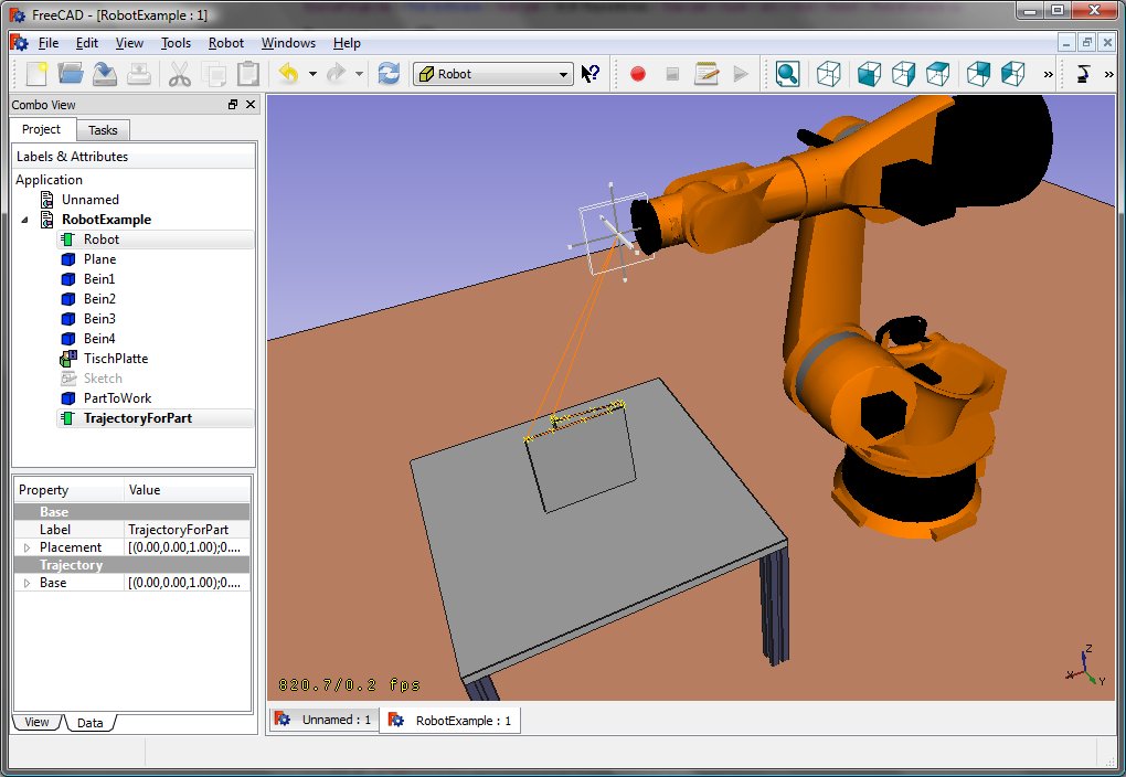
Při konkretizaci robota můžete natáhnout VRML:
App.activeDocument().addObject("Robot::RobotObject","Robot")
App.activeDocument().Robot.RobotVrmlFile = "C:/_Projekte/FreeCAD0.9_build/mod/Robot/Lib/Kuka/kr16.wrl"
což by mělo dát tento výsledek:
KR 210
| Axis Speed | |||||||
|---|---|---|---|---|---|---|---|
| 1 | 0 | 750 | 350 | -90 | -185 | 185 | 156 |
| 2 | 0 | 0 | 1250 | 0 | -155 | 35 | 156 |
| 3 | - 90 | 0 | 0 | 90 | -130 | 154 | 156 |
| 4 | 0 | -1100 | 0 | -90 | -350 | 350 | 330 |
| 5 | 0 | 0 | 0 | 90 | -130 | 130 | 330 |
| 6 | 0 | -230 | 0 | 180 | -350 | 350 | 615 |
KR 500
| Axis Speed | |||||||
|---|---|---|---|---|---|---|---|
| 1 | 0 | 1045 | 500 | -90 | -185 | 185 | 156 |
| 2 | 0 | 0 | 1300 | 0 | -155 | 35 | 156 |
| 3 | - 90 | 0 | 0 | 90 | -130 | 154 | 156 |
| 4 | 0 | -1025 | 0 | -90 | -350 | 350 | 330 |
| 5 | 0 | 0 | 0 | 90 | -130 | 130 | 330 |
| 6 | 0 | -250 | 0 | 180 | -350 | 350 | 615 |
Links
- Springer Handbook of Robotics, section Kinematics, p 9-33.
- Denavit-Hartenberg Parameter 3D Video Tutorial Denavit-Hartenberg Parameter 3D Video Tutorial for a KUKA industry robot on YouTube (german).
- Denavit-Hartenberg Reference Frame Layout Denavit-Hartenberg Reference Frame Layout on YouTube.
- RoboAnalyzer RoboAnalyzer is a 3D model based software that can be used to teach and learn the Robotics concepts.
- Trajectories, non parametric: Create a trajectory, Set default orientation, Set default values, Insert waypoint, Insert waypoint (mouse)
- Trajectories, parametric: Create a trajectory from edges, Dress-up trajectory, Trajectory compound
- Getting started
- Installation: Download, Windows, Linux, Mac, Additional components, Docker, AppImage, Ubuntu Snap
- Basics: About FreeCAD, Interface, Mouse navigation, Selection methods, Object name, Preferences, Workbenches, Document structure, Properties, Help FreeCAD, Donate
- Help: Tutorials, Video tutorials
- Workbenches: Std Base, Arch, Assembly, CAM, Draft, FEM, Inspection, Mesh, OpenSCAD, Part, PartDesign, Points, Reverse Engineering, Robot, Sketcher, Spreadsheet, Surface, TechDraw, Test Framework
- Hubs: User hub, Power users hub, Developer hub


