首选项编辑器
Introduction
FreeCAD的首选项系统位于Edit menu → Preferences。
FreeCAD中的功能被分为不同的模块,每个模块负责实现一种特定workbench的具体工作。 FreeCAD采用的是延迟加载方式,意即只有当需要使用特定组件时才会进行加载。您在FreeCAD的工具栏中选择工作台时可能会注意到这一点,因为在加载工作台及其所有组件时需要花费一点儿时间。在进行首选项设置时也是如此。
在没有加载任何模块时,您可以访问两个配置部分,分别用于应用通用设置(general)与显示设置(display)。当您使用特定的工作台时,便会在新选项卡中显示对应工作台的首选项设置,并在Import-Export新加部分显示该工作台所支持的文件格式。
点击首选项左下角的Reset按钮,即可将FreeCAD中的所有首选项设置还原为其默认值。
Some advanced preferences can only be changed in the Parameter editor. The Fine-tuning page lists some of them.
通用设置
本首选项部分包含6个选项卡:
常规
在General选项卡中,您可以指定下列内容:
| 名称 | 描述 |
|---|---|
| Change language | 选择FreeCAD的用户界面语言 |
| Size of recent file list | 指定有多少最近用过的文件显示在recent files列表中 |
| Enable tiled background | 如果选中此复选框,则FreeCAD的主窗口背景将默认由以下图片填充: 本选项只有在Style sheet/No style sheet被选中时才会生效。 将图片加入到下列路径中的Gui/Images文件夹下即可改变贴图内容 %APPDATA%/FreeCAD (在Windows上), $HOME/.FreeCAD (在Linux上) or $HOME/Library/Preferences/FreeCAD (在MacOS上)。 将图片文件命名为background.png,再依次取消/选中本选项来查看效果。 This option only has an effect if no Style sheet is selected. The image can be changed by adding the folders Gui/Images in the folder: %APPDATA%/FreeCAD (on Windows), $HOME/.FreeCAD (on Linux) or $HOME/Library/Preferences/FreeCAD (on MacOS). Place a file named background.png in the Images folder, and uncheck/check this option to see the changed file. |
| Style sheet | Selection of a style sheet. Style sheets define how the user interface of FreeCAD looks. For technical details about the style sheets, see themes. |
| Size of toolbar icons | Selection of the size for the toolbar icons |
| Tree view mode | Customization how the tree view is shown in the panel (restart required). The options are:
|
| Auto load module after start up | Selection what workbench will be used directly after starting FreeCAD |
| Enable splash screen at start up | If checked, a splash screen is shown when starting FreeCAD.
|
| Style sheet | 选择样式表。样式表定义了FreeCAD用户界面的外观。 |
| Size of toolbar icons | 选择工具栏图标的大小。 |
| Auto load module after start up | 选择FreeCAD开启后将直接打开的工作台。 |
| Enable splash screen at start up | 如果选中此项, 则在FreeCAD开启时展示启动画面。 可通过向%APPDATA%/FreeCAD( %APPDATA%是用户在操作系统中为FreeCAD指定的应用文件夹)添加Gui/Images文件夹来修改启动画面。将作为启动画面的图像命名为splash_image.png并重启FreeCAD即可看到效果。 |
| Enable word wrap | 利用此选项可实现在Python控制台中令超出一行中的文本自动换行。利用View → Panels → Python console菜单来开启Python控制台。 |
文档
在Document选项卡中,您可以指定以下内容:
| 名称 | 描述 |
|---|---|
| Create new document at start up | 如果选中此选项,FreeCAD将在启动时创建一个新文档。 |
| Document save compression level | 指定FCStd文件的压缩级别。FCStd文件为ZIP压缩文件。因此,您可以将其后缀.FCStd改为.zip,并用ZIP归档程序来打开它们。 |
| Using Undo/Redo on documents | 如果选中此选项,所有文档的更改情况将被保存下来,因此即可实现undone/redone。 |
| Maximum Undo/Redo steps | 指定可以记录多少次Undo/Redo操作。 |
| Run AutoRecovery at startup | 如果存在恢复文件,则FreeCAD将在开启时自动运行此文件进行恢复。此法可对程序崩溃时的文件进行恢复。 |
| Save AutoRecovery information every | 指定多久写一次恢复文件。 |
| Save thumbnail into project file when saving document | 如果选中此选项,在保存文档时,也将存储一份项目的缩略图。此缩略图将显示在启动工作台中的最近打开文件列表中。 |
| Add the program logo to the generated thumbnail | 如果选中此选项,则会将FreeCAD程序的logo |
| Maximum number of backup files to keep when resaving document | 如果选中此选项,在保存文档时也会保留备份文件。您可以指定保留备份文件的数量。这些文件中保存的是此前(previously)的文档版本。第一个备份文件的后缀为 .FCStd1, 第二个后缀为.FCStd2,并以此类推。 |
| Allow duplicate object labels in one document | 如果选中此选项,则不同的对象可以使用相同的标签/名称。例如,同一文档中的不同零件与features可用相同的名字。 |
| Author name | 创建的所有文档均采用此指定的作者名。对于匿名作者而言,作者名字的区域为空白内容。若开启了Set on save选项,则在保存文件时将Last modified by的内容设置为此作者名。可通过File → Project information菜单来查看该文本域。 |
| Company | 将创建的所有文档都指定为此公司名称。 |
| Default license | 为新文档所指定的默认许可证。对于预定义的许可证而言,License URL将自动做出对应的设置。而针对自定义许可证或特殊许可证来讲,可选择'Other(其他)'项。 |
| License URL | 指定URL来描述Default license中所选的许可证。 |
| Name | Description |
|---|---|
| Create new document at start up | If checked, FreeCAD will create a new document when started |
| Document save compression level | Specification of the compression level for FCStd files. FCStd files are ZIP-compressed files. Therefore you can rename their suffix .FCStd to .zip and open them with a ZIP archive program. |
| Using Undo/Redo on documents | If checked, all changes in documents are stored so that they can be undone/redone |
| Maximum Undo/Redo steps | Specification how many Undo/Redo steps should be recorded |
| Allow aborting recomputation | If checked, recomputations can be aborted by pressing Esc. This may slightly increase the recomputation time. |
| Run AutoRecovery at startup | If there is a recovery file available FreeCAD will automatically run a file recovery when it is started. This way files can be restored if a crash occurred. |
| Save AutoRecovery information every | Specification how often a recovery file is written. |
| Save thumbnail into project file when saving document | If checked, a thumbnail will be stored when the document is saved. The thumbnail will for example be shown in the list of recent files in the Start workbench. It is possible to select a Size between 128×128 and 512×512 pixels for the thumbnail. Common sizes are the powers of two: 128, 256, 512. |
| Add the program logo to the generated thumbnail | If checked, the FreeCAD program logo |
| Maximum number of backup files to keep when resaving document | If checked, backup files will be kept when saving the document. You can specify the number of backup files to keep. Backup files are previously saved versions of the document. The first backup file will have the file suffix .FCStd1, the second .FCStd2 and so on. |
| Use date and FCBak extension | If checked, backup files will get the extension .FCbak and their file names get a date suffix according to the specified date format. For a description of the date format see this site.
With the default settings a backup file will for example get this name TD-Cube.20200315-215654.FCBak (original filename is TD-Cube.FCStd). |
| Allow duplicate object labels in one document | If checked, objects can have the same label. |
| Disable partial loading of external linked objects | If partial loading of external linked objects is enabled, only the referenced objects and their dependencies will be loaded when the linked document is auto opened together with the main document. Such a partially loaded document cannot be edited. Double click the document icon in the tree view to reload it in full. A more detailed explanation of this feature can be found on the Assembly3 documentation page |
| Author name | All created documents will get the specified author name. Keep the author field blank if you do not want to include this information. If the option Set on save is checked, the field Last modified by will be set to the specified author when saving the file. This field can be viewed using the File → Project information menu option. |
| Company | All created documents will get the specified company name |
| Default license | Selection of the license for new documents. For predefined licenses the License URL will automatically be set accordingly. Select Other for a custom license. |
| License URL | Specification of an URL describing the license selected in Default license |
选择
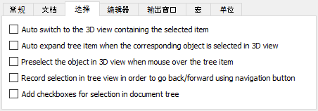
On the Selection tab (introduced in version 0.19) you can specify the following:
| Name | Description |
|---|---|
| Auto switch to the 3D view containing the selected item | Enables the Tree view SyncView mode |
| Auto expand tree item when the corresponding object is selected in 3D view | Enables the Tree view SyncSelection mode |
| Preselect the object in 3D view when mouse over the tree item | Enables the Tree view PreSelection mode |
| Record selection in tree view in order to go back/forward using navigation button | Enables the Tree view RecordSelection mode |
| Add checkboxes for selection in document tree | Each document tree item will get a checkbox. This is for example useful for selecting multiple items on a touchscreen. |
编辑器
编辑器首选项设置影响的是宏编辑器的行为。此编辑器可通过Macro → Macros... → Edit/Create菜单打开。
请注意: 这里的颜色和字体设置也会影响到Python控制台。此控制台可通过View → Panels → Python console菜单打开。
The color and font settings also affect the Python console. This console is shown using the menu View → Panels → Python console.
在Editor选项卡中,您可以指定以下内容:
| 名称 | 描述 |
|---|---|
| Display Items | 选择代码类型。此处的颜色与字体设置将应用于所选的代码类型。可以从Preview框中预览效果。 |
| Family | 指定应用于所选代码类型的字体系列(font family)。 |
| Size | 指定应用于所选代码类型的字体大小。 |
| Enable line numbers | 若开启此项,将显示代码行号。 |
| Tab size | 指定一个tab符占多少空格位置。若将此值设置为'6',则多次按下Tab键后,将根据当前光标位置,依次跳至其后的第7个字符、第13个字符或第19个字符等处。只有在选中Keep tabs后,本选项才可生效。 |
| Indent size | 指定在按下Tab键后将会插入多少个空格。只有在选中Insert spaces后,本选项才会生效。 |
| Keep tabs | 如果选择本项,则按下Tab键将插入占空为Tab size的tab符。 |
| Insert spaces | 如果选择本项,则按下Tab键将插入数量为Indent size的空格符。 |
输出窗口
The output preferences affect the behavior of the Report view. This panel is shown using the menu View → Panels → Report view.
On the Output tab you can specify the following:
| Name | Description |
|---|---|
| Record normal messages | If checked, normal messages will be recorded. They will be displayed in the Report view with the color set in 正常的消息. |
| 记录日志 | If checked, log messages will be recorded. They will be displayed in the Report view with the color set in 日志信息. |
| 记录警告 | If checked, warnings will be recorded. They will be displayed in the Report view with the color set in 警告. |
| 记录错误 | If checked, error messages will be recorded. They will be displayed in the Report view with the color set in 错误. |
| 错误时显示报表视图 | If checked, the Report view will be shown automatically when an error is recorded |
| 在警告时显示报告视图 | If checked, the Report view will be shown automatically when a warning is recorded |
| Show report view on normal message | If checked, the Report view will be shown automatically when a normal message is recorded |
| 在日志消息中显示报告视图 | If checked, the Report view will be shown automatically when a log message is recorded |
| Include a timecode for each entry | If checked, each message and warning will receive a timecode |
| 正常的消息 | Specification of the font color for normal messages |
| 日志信息 | Specification of the font color for log messages |
| 警告 | Specification of the font color for warning messages |
| 错误 | Specification of the font color for error messages
|
| 将 Python 内部输出重定向到报告视图 | If checked, internal Python output will be redirected from the Python console to the Report view |
| 将 Python 内部错误重定向到报告视图 | If checked, internal Python error messages will be redirected from the Python console to the Report view |
宏
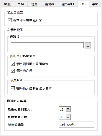
On the Macro tab you can specify the following:
| Name | Description |
|---|---|
| 在本地环境中运行宏 | If checked, variables defined by macros are created as local variables, otherwise as global Python variables |
| 宏路径 | Specification of the path for macro files |
| 录制图形用户界面命令 | If checked, recorded macros will also contain user interface commands |
| 录制为注释 | If checked, recorded macros will also contain user interface commands, but as comments. This is useful if you don't want to execute these commands when running the macro, but do want to see what has been done while recording. |
| 在Python控制台显示脚本 | If checked, the commands executed by macro scripts are shown in the Python console. This console is shown using the View → Panels → Python console menu option. |
| Size of recent macros list | Controls the number of recent macros to display in the menu |
| 快捷方式计数 | Controls the number of recent macros that get dynamically assigned shortcuts |
| 键盘编辑器 | Controls which keyboard modifiers are used for the shortcuts, example Ctrl+Shift+ creates shortcuts in the form of Ctrl+Shift+1, Ctrl+Shift+2, etc. |
单位
On the Units tab you can specify the following:
| Name | Description |
|---|---|
| User system | Selection of the unit system to be used for all parts of FreeCAD |
| 小数位数︰ | The number of decimals that should be shown for numbers and dimensions |
| 最小分数英寸: | 最小分数英寸: that should be displayed. This setting is only available if the unit system Building US (ft-in/sqft/cuft) is used. |
Display settings
This preferences section has three standard tabs: 3D View, Navigation and Colors. A fourth tab, Mesh view, is added if the Mesh Workbench has been loaded.
三维视图
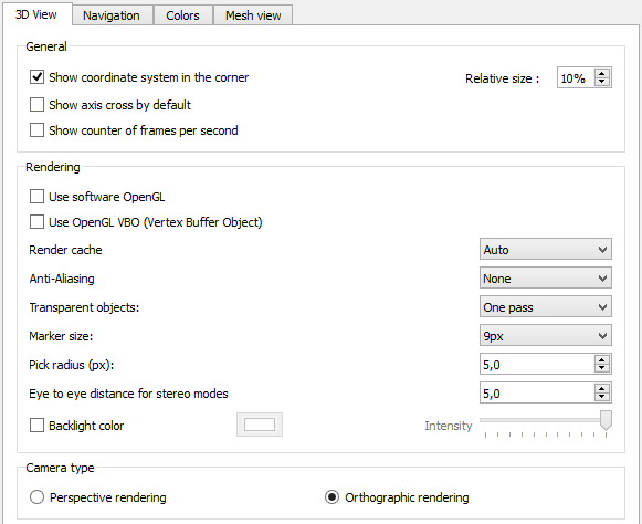
On the 3D View tab you can specify the following:
| Name | Description |
|---|---|
| Show coordinate system in the corner | If checked, the main coordinate system will always be shown at the lower right in opened files |
| Show axis cross by default introduced in version 0.19 | If checked, the axis cross will be shown by default at file opening or creation |
| Show counter of frames per second | If checked, the time needed for the last operation and the resulting frame rate will always be shown at the lower left in opened files |
| Remember active workbench by tab introduced in version 0.19 | If checked, the application will remember the active workbench for each tab in the Main view area independently. When switching to a tab this workbench will be restored automatically. |
| Use software OpenGL introduced in version 0.19 | If checked, OpenGL will use the CPU instead of the GPU. This option is useful for troubleshooting graphics card and driver problems. Changing this option requires a restart of the application. |
| Use OpenGL VBO (Vertex Buffer Object) | If checked, Vertex Buffer Objects (VBO) will be used. A VBO is an OpenGL feature that provides methods for uploading vertex data (position, normal vector, color, etc.) to the graphics card. VBOs offer substantial performance gains because the data resides in the graphics memory rather than the system memory and so it can be rendered directly by the GPU. For more background info see this webpage. |
| Render Cache introduced in version 0.19 | "Render Cache" or "Render Acceleration" is explained in more detail in FreeCAD_assembly3 render-caching. There are 3 options:
|
| Anti-Aliasing | Selection if and what kind of multisample anti-aliasing is used |
| Transparent objects introduced in version 0.19 | Render type of transparent objects. The types are:
|
| Marker size | Selection of the size of vertices (points) in the Sketcher workbench. The clickable area of points can be additionally enlarged by increasing the Pick radius. |
| Pick radius (px) | Sets the area for picking elements in the 3D view. Larger value makes it easier to pick things, but can make some small features impossible to select. |
| Eye to eye distance for stereo modes | Specification of the eye-to-eye distance used for stereo projections. The specified value is a factor that will be multiplied with the bounding box size of the 3D object that is currently displayed. |
| Backlight color | If checked, backlight is enabled with the defined color. Backlight is used for rendering back sides of faces. Usually, you don't see them in solids, unless you slice one with a clipping plane, or if the faces aren't oriented correctly. It is only active for objects whose Lighting property (on the View tab) is set to One side. If disabled, back sides of faces of objects in One side lighting mode will be black.
The related Intensity setting specifies the intensity of the backlight. |
| Camera type | Selection of the camera projection type.
|
导航栏
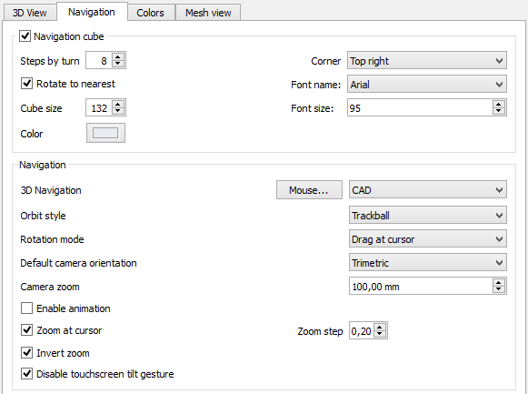
On the Navigation tab you can specify the following:
| Name | Description |
|---|---|
| Navigation cube | If checked, the Navigation cube will always be shown.
Steps by turn defines the number of steps required for a full rotation when using the Navigation cube rotation arrows. Corner defines where the Navigation cube is displayed on the screen when creating or opening a document. If Rotate to nearest is checked, the 3D view is rotated to the nearest most logical state when a cube face is clicked. When it is off, clicking to a cube face will and up always to the same position, no matter in what cube state you were when you clicked the face. introduced in version 0.20 Cube size defines the size of the cube. introduced in version 0.20 |
| 3D Navigation | Selection of a navigation settings set. To see what each set defines, select it and then press the Mouse... button. |
| Orbit style | Selection of the rotation orbit style. When viewing a part in the x-y plane and being in the rotation mode of the 3D navigation, the difference is: If Trackball is selected, moving the mouse horizontally will rotate the part around the y-axis, if Turntable is selected the part will be rotated around the z-axis. |
| Rotation mode | Defines the rotation center. Select Window center, Drag at cursor, or Object center. |
| Default camera orientation | Selection of the camera orientation for new documents. This setting is also used by the Std ViewHome command. |
| New document scale | Affects the initial camera zoom level for new documents. The value you set is the diameter of a sphere that fits in 3D view. Default is 100 mm. It also sets the initial size of origin features (base planes in new PartDesign Bodies). |
| Enable animation | If checked, rotations can be animated. If for example the 3D Navigation set CAD is used and the mouse is moved while the scroll wheel and the right mouse button are pressed, parts are rotated. If one keeps the mouse moving while releasing e.g. the right mouse button, the rotation will continue as animation. To end the animation left-click with the mouse. |
| Zoom at cursor | If checked, zoom operations will be performed at the position of the mouse pointer. Otherwise zoom operations will be performed at the center of the current view. The Zoom step defines how much will be zoomed. A zoom step of 1 means a factor of 7.5 for every zoom step. |
| Invert zoom | If checked, the direction of zoom operations will be inverted |
| Disable touchscreen tilt gesture | If checked, the tilting gesture will be disabled for pinch-zooming (two-finger zooming). This only affects the 3D Navigation set Gesture. |
颜色
On the Colors tab you can specify the following:
| Name | Description |
|---|---|
| Enable preselection highlighting | If checked, preselection is turned on and the specified color will be used for it. Preselection means that for example edges in parts will be highlighted while hovering over them with the mouse to indicate they can be selected. |
| Enable selection highlighting | If checked, selection highlighting is turned on and the specified color will be used for it |
| Simple color | If selected, the background of the 3D view will have the selected color |
| Color gradient | If selected, the background of the 3D view will have a vertical color gradient. The first color is the color at the top of the 3D view, the second the color at the bottom. |
| Middle color | Is only enabled if Color gradient is selected. If checked, the color gradient will get the selected color as the middle color. |
| Object being edited | Selection of the background color for objects in the tree view that are currently edited |
| Active container | Selection of the background color for active containers in the tree view. For example an active PartDesign Body will get the selected background color. |
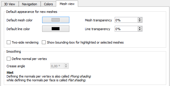
网格视图
This tab is only available if the Mesh Workbench has been loaded.
On the Mesh view tab you can specify the following:
| Name | Description |
|---|---|
| Default mesh color | Selection of the default shape color |
| Default line color | Selection of the default line color |
| Mesh transparency | Specification of the default mesh transparency |
| Line transparency | Specification of the default line transparency |
| Two-side rendering | If checked, the color of the interior side of faces will be the same as the exterior side. If not checked either the backlight color, if enabled, or black will be used instead. |
| Show bounding-box for highlighted or selected meshes | If checked, a yellow bounding box will be displayed for highlighted or selected meshes |
| Define normal per vertex | If checked, Phong shading is used, otherwise flat shading. Shading defines the appearance of surfaces. With flat shading the surface normals are not defined per vertex. This leads to an unrealistic appearance for curved surfaces. While Phong shading leads to a more realistic, smoother appearance. |
| Crease angle | The crease angle is a threshold angle between two faces. It can only be set if the option Define normal per vertex is used.
|
Workbenches
This preferences section has a single tab: Unloaded Workbenches.
Unloaded Workbenches
To preserve resources, FreeCAD does not automatically load all available workbenches. And only if a workbench has been loaded will its preferences, if any, appear in the Preferences editor.
The Unloaded Workbenches tab displays a list of installed workbenches that have not yet been loaded. To load one or more workbenches select them in the list and then press the Load Selected button. If a newly loaded workbench has dedicated preference they will appear in a new section in the Preferences editor. Some workbenches add support for additional import and export formats. If there are any related preferences they will appear on one or more new tabs in the Import-Export settings section of the Preferences editor.
For a list of workbench preferences see Workbench preferences
File:Preferences Workbenches Tab Unloaded Workbenches.png
Import-Export settings
The Import-Export settings affect how files are imported and exported. They are described on the Import Export Preferences page.
工作台首选项
下列为常用工作台的首选项。部分工作台并没有对应的首选项。其他可选工作台可能也未列入其中。
Preferences for the more common workbenches are linked below. Some workbenches have no preferences. Other optional workbenches may not be listed. These links are also listed in Category:Preferences
External workbenches
Scripting
Preferences can be accessed from Python scripts using their corresponding path in the Parameter Editor. For example, the Edit → Preferences → Import-Export → DXF → Import options → Join geometry preference appears in Tools → Edit parameters → BaseApp → Preferences → Mod → Draft → dxfCreatePart and has type Boolean. It can therefore be accessed in Python using the following code:
# get:
App.ParamGet("User parameter:BaseApp/Preferences/Mod/Draft").GetBool('dxfCreatePart')
# set:
App.ParamGet("User parameter:BaseApp/Preferences/Mod/Draft").SetBool('dxfCreatePart', True)
Finding which parameter is used to store which option from the Preferences editor can require searching a bit, but the Parameter Editor offers a search facility, which should help.
It is likely a bad idea to modify the preferences of other parts of FreeCAD unless doing so at the user's request. The setter can however be used to set parameters for your own workbench, and the getter can be used to obey existing parameters.
Related
- Getting started
- Installation: Download, Windows, Linux, Mac, Additional components, Docker, AppImage, Ubuntu Snap
- Basics: About FreeCAD, Interface, Mouse navigation, Selection methods, Object name, Preferences, Workbenches, Document structure, Properties, Help FreeCAD, Donate
- Help: Tutorials, Video tutorials
- Workbenches: Std Base, Assembly, BIM, CAM, Draft, FEM, Inspection, Mesh, OpenSCAD, Part, PartDesign, Points, Reverse Engineering, Robot, Sketcher, Spreadsheet, Surface, TechDraw, Test Framework
- Hubs: User hub, Power users hub, Developer hub


