Posizionamento
Descrizione
Placement (Posizionamento) è la funzione utilizzata da FreeCAD per specificare la localizzazione (dove si trova) e l'assetto (orientamento) di un oggetto nello spazio. Placement può essere specificato in diversi modi e manipolato tramite script, tramite la scheda delle Proprietà oppure il dialogo Placement del menu Modifica.
Accedere agli attributi di Placement
Gli attributi di Posizionamento di un oggetto sono accessibili in tre modi:
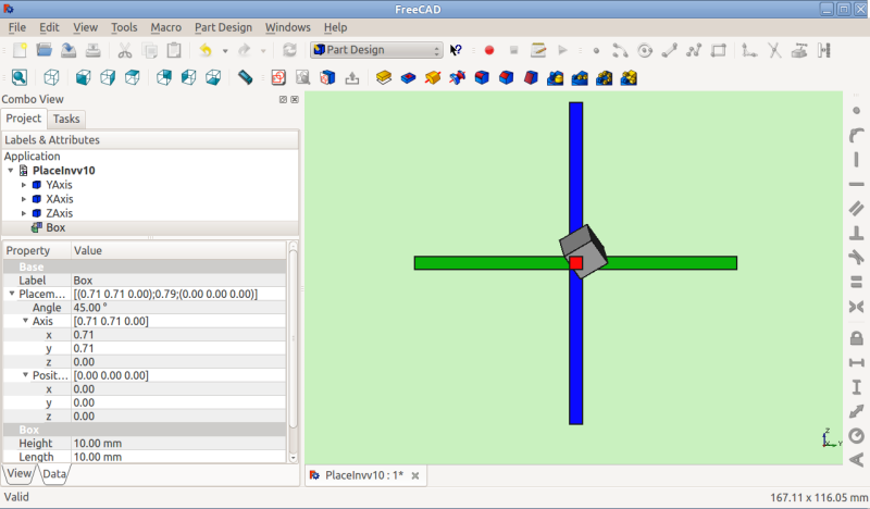

Il menu Modifica Posizionamento
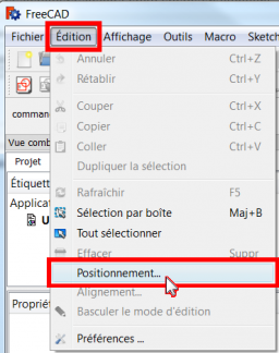
che apre e mostra lo strumento Azioni di Posizionamento.
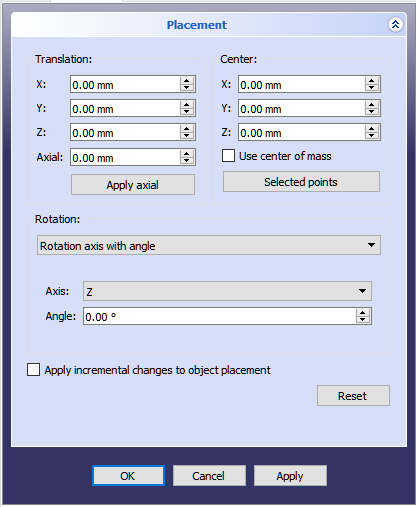
Tipi di posizionamento
Internamente il posizionamento viene memorizzato come una posizione, e una rotazione (asse di rotazione e angolo trasformati in un quaternione [1]). Sebbene ci siano diversi modi di specificare una rotazione, per esempio con un centro di rotazione, questo è usato solo per influenzare il calcolo della rotazione e non viene memorizzato per le operazioni successive. Allo stesso modo, se viene specificato un asse di rotazione (1,1,1), esso può essere normalizzato se conservato nel quaternione e in seguito apparire nella forma (0.58, 0.58, 0.58) durante l'esplorazione dell'oggetto
Angolo, Assi e Posizione
Placement=[Angle, Axis, Position]
La prima forma di Placement stabilisce la Posizione di un oggetto nello spazio e descrive il suo orientamento come una singola rotazione attorno ad un asse.
Angle = r : è uno scalare che indica la quantità di rotazione dell'oggetto su Axis. Inserito in gradi, ma memorizzato internamente in radianti.
Axis = (ax,ay,az) : è un vettore unitario che descrive un asse di rotazione (vedere Nota relativa all'asse di rotazione).
Esempi:
   (1,0,0)       ==> sull'asse X
   (0,1,0)       ==> sull'asse Y
   (0,0,1)       ==> sull'asse Z
   (0.71,0.71,0) ==> sulla linea y=x
Note that it is also possible to translate (move) an object along this axis of rotation (axial motion) by entering the distance to move in the Axial spinbox and clicking the Apply axial button. (One way to envision axial motion is to think of an airplane with a propeller spinning on its nose -- the propeller spins about an axis of rotation while the plane moves along that same axis.) The values in the vector can be thought of as the relative amount of motion that will be applied in that direction. For example, in the y=x case (0.71,0.71,0) the value contained in the Axial spinbox gets applied in equal measure to the X and Y directions, but no movement happens in the Z direction.
Position = (x,y,z) is a Vector describing the point from which the object's geometry will be calculated (in effect, a "local origin" for the object). Note that in scripts, Placement.Base is used to denote the Position component of a placement. The Property Editor calls this value "Position" and the Placement dialog calls it "Translation".
Posizione con Imbardata, Beccheggio e Rollio
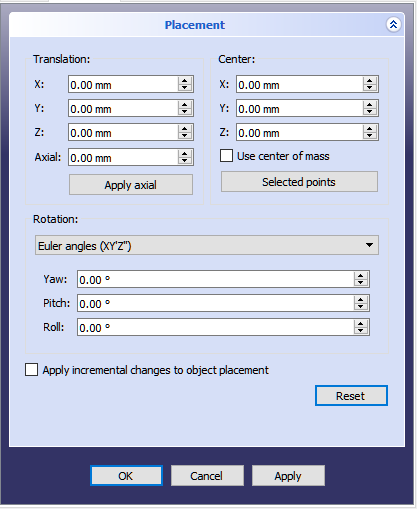
Placement = [Position, Yaw-Pitch-Roll]
La seconda forma di Placement fissa la posizione di un oggetto nello spazio con Position (come nella prima forma), ma descrive il suo orientamento con gli angoli di imbardata, beccheggio e rollio. Questi angoli sono anche denominati angoli Tait-Bryan o angoli di Eulero. Imbardata, beccheggio e rollio sono termini comuni nel settore dell'aviazione per descrivere l'orientamento (assetto) del veicolo.
Position = (x,y,z) è un vettore che descrive il punto da cui sarà calcolata la geometria dell'oggetto (di fatto, una "origine locale" per l'oggetto).
Yaw-Pitch-Roll = (y,p,r) è una tupla che definisce l'assetto dell'oggetto. I valori di y, p, r, specificano i gradi di rotazione intorno agli assi z, y, x, vedere le Note.
>>> App.getDocument("Sans_nom").Cylinder.Placement=App.Placement(App.Vector(0,0,0), App.Rotation(10,20,30), App.Vector(0,0,0))
App.Rotation(10,20,30) = Angoli di Eulero
Yaw = 10 gradi (Z)
Pitch = 20 gradi (Y)
Roll = 30 gradi (X)
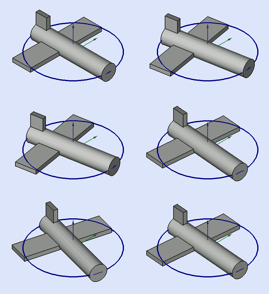
Yaw è la rotazione intorno all'asse Z, destra sinistra e viceversa.
Angolo Psi ψ.
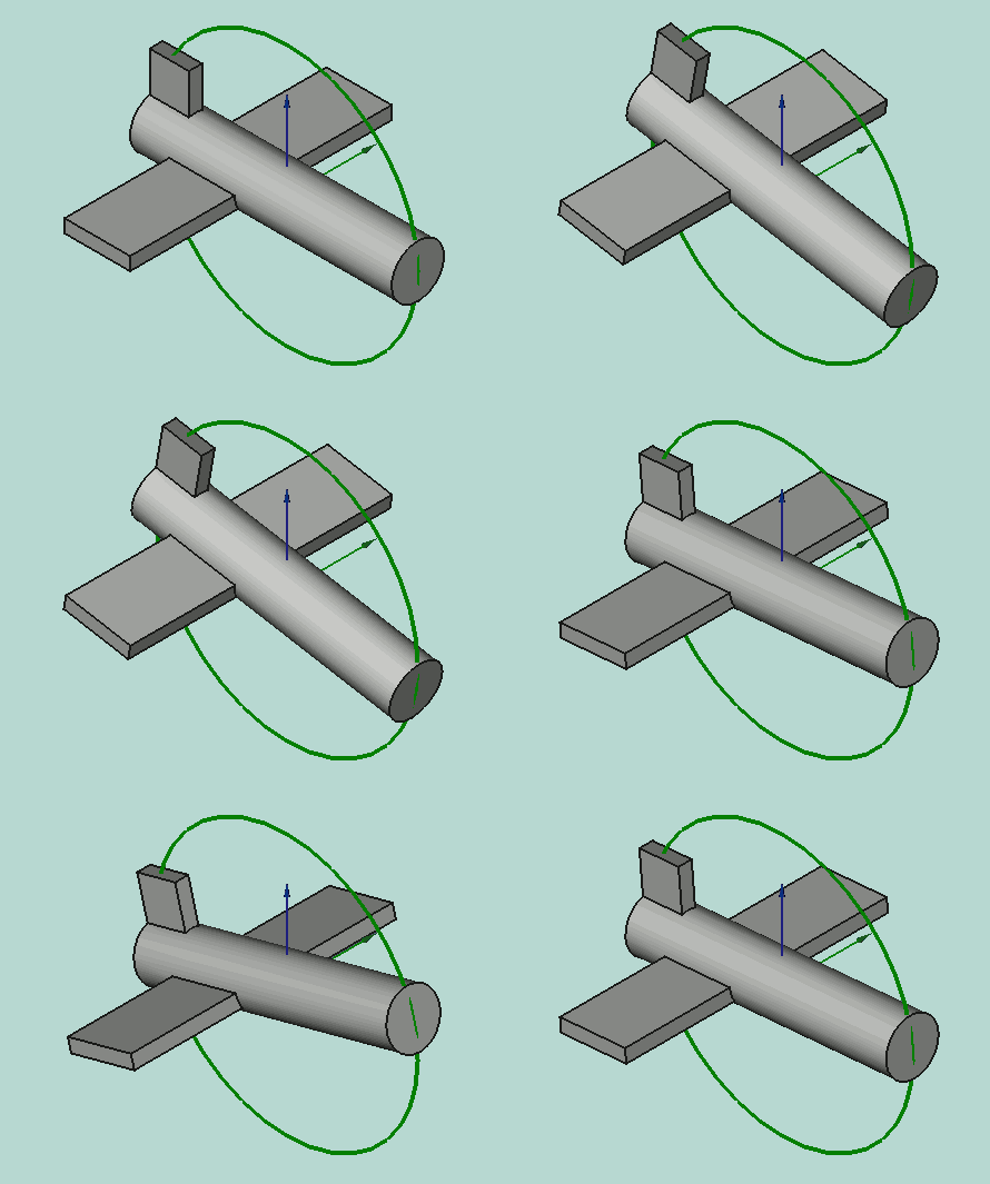
Pitch è la rotazione intorno all'asse Y, alzare o abbassare il naso.
Angolo Phi φ.
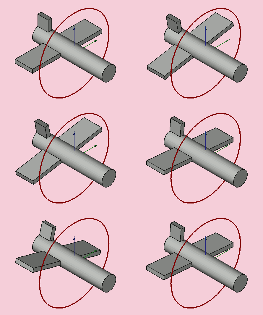
Roll è la rotazione intorno all'asse X, dondolare le ali.
Angolo Thêta θ.
Matrice
Placement = Matrix
La terza forma di Placement descrive la posizione dell'oggetto e l'orientamento con una matrice 4x4 di Trasformazione Affine.
Matrix =
  ((r11,r12,r13,t1),
   (r21,r22,r23,t2),
   (r31,r32,r33,t3),
   (0,0,0,1)) , dove rij specifica la rotazione e ti specifica la traslazione.
La finestra di dialogo Posizionamento
La finestra di dialogo Posizionamento viene richiamata dal menu Modifica. E' utilizzata per ruotare o traslare con precisione gli oggetti. E' anche usata quando si deve creare uno schizzo su un piano "non standard" o per modificare l'orientamento di un disegno in un nuovo piano.
La sezione Traslazione regola la posizione degli oggetti nello spazio.
La sezione Centro imposta singolarmente gli assi di rotazione che non passano attraverso il punto di riferimento dell'oggetto. La sezione Rotazione imposta l'angolo, o gli angoli di rotazione e il metodo per specificare tali angoli.
Selezionare la casella Applica le modifiche incrementali al posizionamento dell'oggetto è utile quando le traslazioni o le rotazioni devono essere effettuate rispetto alla posizione o all'assetto relativo corrente dell'oggetto, invece che rispetto alla posizione o all'assetto originale. Quando questa casella viene selezionata i valori dei campi di input della finestra di dialogo vengono reimpostati a zero, ma non si modifica l'orientamento dell'oggetto o la sua posizione. Successivi reimpostamenti modificano l'orientamento o la posizione, ma vengono applicati a partire dalla posizione corrente dell'oggetto.
Esempi
But while the elements within each section generally apply to the purpose of that section there are also some elements in one section that can affect elements in another section. For example, clicking the Selected points button in the Center section with 2 points selected in the 3d view results in not only populating the Center coordinate spinboxes with the coordinates of the midpoint between those 2 selected points, but it also creates a custom axis along the line defined by those 2 selected points in the Rotation section. In another example, placing a value in the Axial spinbox and clicking the Apply axial button in the Translation section translates (moves) the object along the axis defined in the Rotation section.
The Apply incremental changes to object placement tick box is useful when translations/rotations are to be made relative the object's current position/attitude, rather than to the original position/attitude. Ticking this box resets the dialogue input fields to zero, but does not change the object's orientation or location. Subsequent entries do change the orientation/location, but are applied from the object's current position. Enabling this checkbox is also useful when using the Selected points button as it can sometimes prevent undesired placement changes.
PS: poiché la versione 0.17 introduce una nuova parte dell'oggetto, questo oggetto ha il suo posizionamento e l'oggetto di posizionamento creato nell'oggetto Part viene incrementato con il Posizionamento del obietto Part. disponibile dalla versione 0.17 Per ottenere il piazzamento del obietto Part usa questo codice:
import Draft, Part
sel = FreeCADGui.Selection.getSelection()
print sel[0].Placement
print sel[0].getGlobalPlacement()   # return the GlobalPlacement
print sel[0].getParentGeoFeatureGroup() # return the GeoFeatureGroup, ex:  Body or a Part.
print  "____________________"
Selected points button is used to populate the coordinates in the Center coordinates spinboxes and (when 2 or 3 points are selected) additionally to create a custom (user-defined) axis of rotation in the Rotation section. A point can be a vertex, but it can also be any point along an edge or on a face. When you select an edge or face the entire edge or face is selected, but FreeCAD also remembers which point on that face or edge the mouse pointer was hovering over when that edge or face was selected. It is this point's coordinates that get used in the Placement dialog when the Selected points button is clicked. You might be thinking this isn't a very precise way of selecting a point, and you are correct, but in many cases it is sufficient that the point selected is guaranteed to be on that edge or face. In cases where you need to precisely designate a point to be used you should select a vertex. When there is no vertex in the desired location consider creating one, perhaps in a temporary sketch attached to that face or edge, perhaps using a Draft workbench object, such as a line or point, etc.
Let us first consider the simple case of selecting 1 point. The workflow is to first select the desired point, then click the Selected points button. The coordinates of the selected point will be used to populate the X, Y, and Z spinboxes within the Center section. Now any rotation done on the object will about this center of rotation.
Now consider the case of selecting 2 points. You would select the 2 desired points, and then click the Selected points button. The coordinates of the midpoint between the 2 selected points get placed into the X, Y, and Z spinboxes within the Center section. Now any rotation done on the object will be about this center of rotation. But in addition to setting up the Center section coordinates a custom (user-defined) axis is also added to the Axis element within the Rotation section. (Note: if you were in Euler rotation mode, the mode gets switched to Rotation with an axis mode and the new custom axis is selected as the current axis of rotation.) Now any rotation done using the new custom axis will be about this axis of rotation. As an added bonus, the distance is measured between the 2 selected points, and this information is given in the Report View. By entering this distance into the Axial spinbox in the Translation section and clicking the Apply axial button you can translate (move) the object so that the first selected point now occupies the coordinates occupied by the second selected point (at the time the Selected points button was clicked).
Now consider the case of selecting 3 points. You would select the 3 desired points, and then click the Selected points button. The coordinates of the first selected point (order of selection is very important here) get placed into the X, Y, and Z spinboxes within the Center section. Since 3 points define a plane FreeCAD is able to take advantage of that and use those 3 points to create a new custom (user-defined) axis of rotation that is normal (perpendicular) to that defined plane. As with 2 selected points, the distance between points is also shown in the Report View, but this time it is the distance between the 2nd and 3rd selected points. Additionally, the angle between the 2nd and 3rd points is also measured and displayed in the Report View. By entering this angle into the Angle spinbox within the Rotation section we can very precisely rotate the object such that now the 2nd selected point is in alignment with the coordinates occupied by the 3rd selected point. (Note: you might want to increase the number of digits used within the Edit menu -> Preferences -> General -> Units -> Number of decimals spinbox if you desire more precision.)
Esempio
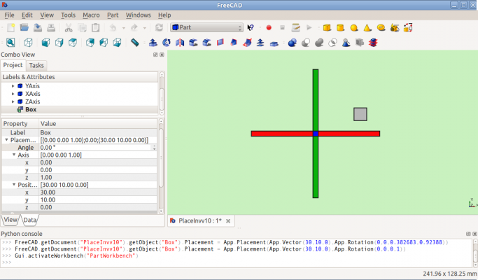
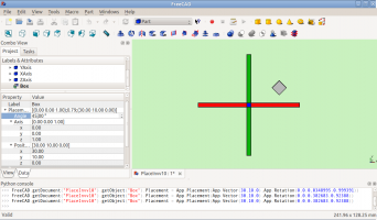
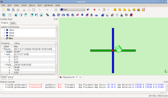
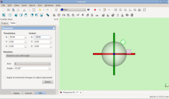
Rotazione su un singolo asse:
-
Prima della rotazione (Vista dall'alto)
-
Dopo la rotazione rispetto all'asse Z (Vista dall'alto)
-
Prima della rotazione rispetto a y=x (Vista da destra)
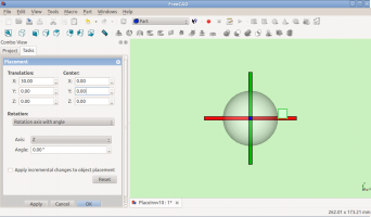
Rotazione con scostamento del punto centrale:
-
Prima della rotazione (Vista dall'alto)
-
Dopo la rotazione rispetto all'asse Z (Vista dall'alto)
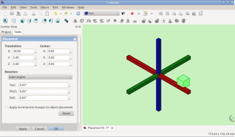
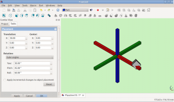
Rotazione con impiego degli angoli di Eulero:
-
Prima della rotazione
-
Dopo la rotazione
Placement.Base vs Shape Definition
Placement non è l'unico modo per posizionare una forma nello spazio. Notare la console Python in questa immagine:

Entrambi i cubi hanno lo stesso valore per il Placement, ma si trovano in luoghi diversi! Questo perché le due forme sono definite da differenti vertici (curve in forme complesse). Per le due forme della figura sopra:
   >>> ev = App.ActiveDocument.Extrude.Shape.Vertexes
 >>> for v in ev: print v.X,",",v.Y,",",v.Z
 ...
 30.0,30.0,0.0
 30.0,30.0,10.0
 40.0,30.0,0.0
 40.0,30.0,10.0
 40.0,40.0,0.0
 40.0,40.0,10.0
 30.0,40.0,0.0
 30.0,40.0,10.0
 >>> e1v = App.ActiveDocument.Extrude001.Shape.Vertexes
 >>> for v in e1v: print v.X,",",v.Y,",",v.Z
 ...
 0.0,10.0,0.0
 0.0,10.0,10.0
 10.0,10.0,0.0
 10.0,10.0,10.0
 10.0,0.0,0.0
 10.0,0.0,10.0
 0.0,0.0,0.0
 0.0,0.0,10.0
 >>>
I Vertices (o Vectors) che definiscono la forma usano gli attributi Placement.Base per la loro origine.
Quindi, se si desidera spostare una forma di 10 unità lungo l'asse X, si può aggiungere 10 alla coordinata X di tutti i Vertices oppure è possibile impostare Placement.Base a (10,0,0).
Controllare l'asse di rotazione con Centro di Posizionamento
Per impostazione predefinita, l'asse di rotazione non è effettivamente l'asse x, y o z. Si tratta di una linea parallela all'asse selezionato che passa per il punto definito da Placement.Base dell'oggetto da ruotare. Questa impostazione può essere modificata utilizzando i campi Centro della finestra di dialogo Posizionamento oppure, negli script, utilizzando il parametro centre nella costruzione di FreeCAD.Placement.
Si supponga, ad esempio, di avere un cubo (figura sotto) posizionato in (20,20,10).
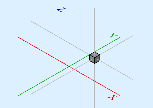
Volendo ruotare il cubo attorno al proprio asse verticale (l'asse locale Z), mantenendolo nella stessa posizione. E' possibile ottenere facilmente questo specificando nei campi Centro un valore corrispondente alle coordinate del punto centrale del cubo (25,25,15).

import FreeCAD
obj = App.ActiveDocument.Box                       # our box
rot = FreeCAD.Rotation(FreeCAD.Vector(0,0,1),45)   # 45° about Z
#rot = FreeCAD.Rotation(FreeCAD.Vector(1,0,1),45)   # 45° about X and 45° about Z
#rot = FreeCAD.Rotation(10,20,30)                   # here example with Euler angle Yaw = 10 degrees (Z), Pitch = 20 degrees (Y), Roll = 30 degrees (X)
centre = FreeCAD.Vector(25,25,15)                  # central point of box
pos = obj.Placement.Base                           # position point of box
newplace = FreeCAD.Placement(pos,rot,centre)       # make a new Placement object
obj.Placement = newplace                           # spin the box
Alcuni script con i file di esempio: RotateCoG2.fcstd (discussion on the forum)
import FreeCAD
obj = App.ActiveDocument.Extrude                    # our box
rot = FreeCAD.Rotation(FreeCAD.Vector(0,0,1),45)    # 45 about Z
#rot = FreeCAD.Rotation(FreeCAD.Vector(1,0,1),45)    # 45° about X and 45° about Z
#rot = FreeCAD.Rotation(10,20,30)                    # here example with Euler angle Yaw = 10 degrees (Z), Pitch = 20 degrees (Y), Roll = 30 degrees (X)
centre = FreeCAD.Vector(25,25,0)                    # "centre" of rotation (where local Z cuts XY)
pos = obj.Placement.Base                            # original placement of obj
newplace = FreeCAD.Placement(pos,rot,centre)        # make a new Placement object
obj.Placement = newplace                            # spin the box
Note
- Assi e Angolo possono anche essere espressi con un quaternione.
- Il punto di riferimento di un oggetto varia a seconda dell'oggetto. Alcuni esempi di oggetti di uso comune:
| Oggetto | Punto di riferimento |
|---|---|
| Part.Box | vertice sinistro (minimo x), frontale (minimo y), in basso (minimo z) |
| Part.Sphere | centro della sfera (centro del suo contenitore cubico) |
| Part.Cylinder | centro della faccia di base |
| Part.Cone | centro della faccia di base (o superiore se il raggio della faccia di base vale 0) |
| Part.Torus | centro del toro |
| Caratteristiche derivate da Sketch | la caratteristica eredita la posizione dello schizzo sottostante. Lo schizzo inizia sempre con Position = (0,0,0). |
Limitazioni
- A partire dalla versione 0.13, l'aggiornamento delle proprietà Placement nella scheda Dati è stato disattivato per gli oggetti creati con PartDesign, fatta eccezione per il disegno iniziale da cui il solido verrà creato.
Pertanto, il posizionamento di un solido creato in PartDesign da uno schizzo può essere modificato solo regolando i parametri di posizionamento del disegno di costruzione iniziale (il primo schizzo) da cui il solido viene creato.
- Le funzionalità di Posizionamento saranno eventualmente trattate nell'ambiente Assemblaggio.
Per saperne di più
- Il tutorial Aeroplano tratta ampiamente sul meccanismo di modifica dell'assetto di un oggetto.
- Una descrizione dettagliata della funzione Placement si trova nella pagina Azioni di Posizionamento.
