Umístění
Celkový pohled
Umístění je vlastnost FreeCADu, která specifikuje místo a směr objetu v prostoru. Umístění může být specifikováno ve více formulářích a může být měněno pomocí skriptů v poli vlastnosti nebo v dialogovém okně Umístění dialog (menu Úpravy).
Přístup k atributu Umístění
K atributům objektu Umístění lze přistupovat a modifikovat je 3 způsoby:

Tvary zadání umístění
Úhel, Osa a Pozice
Umístění = [Úhel, Osa, Pozice]
První ztvar zadání Umístění ustaví místo objektu v prostoru na Pozici a popíše jeho směr jako pootočení kolem osy.
Úhel = r je skalární hodnota udávající velikost pootočení objektu kolem osy. Zadává se ve stupních, ale interně je zaznamenán v radiánech.
Osa = (ax,ay,az) je vektor popisující osu otáčení (Přečtěte si poznámku o ose otáčení). Příklady:
   (1,0,0)       ==> kolem osy X
   (0,1,0)       ==> kolem osy Y
   (0,0,1)       ==> kolem osy Z
   (0.71,0.71,0) ==> kolem přímky y=x
Pozice = (x,y,z) je vektor popisující souřadnice referenčního bodu objektu. Všimněte si, že ve skriptu Placement.Base je použit pro vyznačení komponenty pozice umístění. Editor vlastností zobrazuje tuto hodnotu jako "Pozice".
Pozice a Yaw, Pitch and Roll
Umístění = [Pozice, Yaw-Pitch-Roll]
Druhý tvar zadání Umístění ustaví místo objektu v prostoru pomocí Pozice (stejně jako předchozí tvar),ale popíše jeho orientaci použitím úhlů Yaw, Pitch a
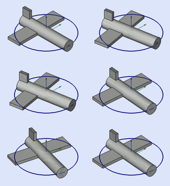
Roll (Yaw, Pitch, Roll). Tyto úhly jsou někdy také nazývány jako Eulerovy úhly nebo Tait-Bryanovy úhly (Eulerovy úhly). Yaw, Pitch a Roll jsou běžně užívány v letecké terminologii pro orientaci (nebo polohy) tělesa.
Pozice = (x,y,z) je vektor popisující souřadnice referenčního bodu objektu.
Yaw-Pitch-Roll = (y,p,r) is a tuple that specifies the attitude of the object. Values for y,p,r specify degrees of rotation about each of the z,y,x axis (see note).
-
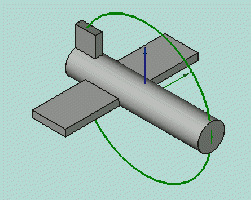
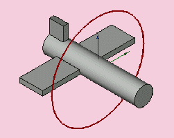
Yaw is the rotation about the Z axis, that is to say a rotation from left to right.
(The yaw angle is the Psi ψ). -
Pitch is rotation about the Y axis, that is to say nose-up and nose-down.
(The Pitch angle is the Phi φ). -
Roll is rotation about the X axis, that is to say wing up and down.
(The Roll angle is the Thêta θ).
Matrix (matice)
Umístění = Matrix
Třetí tvar zadání Umístění popisuje pozici a orientaci objektu pomocí 4x4 afinní transformační matice (Affine Transformation).
Matrix (matice) =
  ((r11,r12,r13,t1),
   (r21,r22,r23,t2),
   (r31,r32,r33,t3),
   (0,0,0,1)) , kde rij specifikuje rotaci a ti specifikuje transformaci.
Dialogové okno umístění
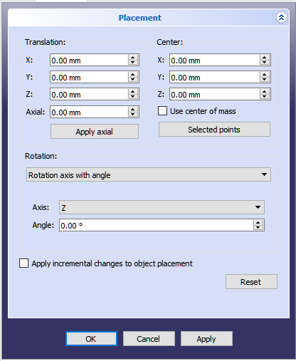
Dialogové okno umístění se spouští z menu Úpravy. Je využíváno pro přesné pootočení a posunutí objektů. Je využíváno také když je potřeba vytvořit náčrt v "nestandardní" rovině nebo změnit orientaci náčrtu v nové rovině.
Sekce Posunutí určuje místo objektu v prostoru. Sekce Střed určuje umístění rotační osy bodem, který neprochází referenčním bodem objektu. The Rotation section adjusts the rotational angle(s) and the method of specifying those angles.
The Apply incremental changes to object placement tick box is useful when translations/rotations are to be made relative the object's current position/attitude, rather than to the original position/attitude. Ticking this box resets the dialog's input fields to zero, but does not change the object's orientation or location. Subsequent entries do change the orientation/location, but are applied from the object's current position.
Examples
Rotations about a single axis:
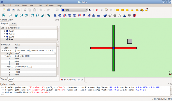
Before Rotation (top view)
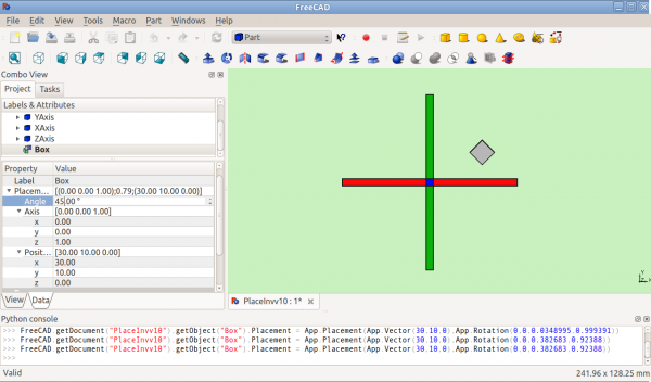
After Rotation about Z (top view)
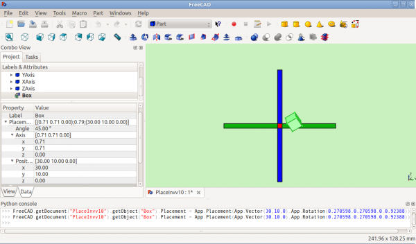
After Rotation about y=x (right view)
Rotation with offset centre point:
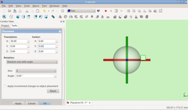
Before Rotation (top view)
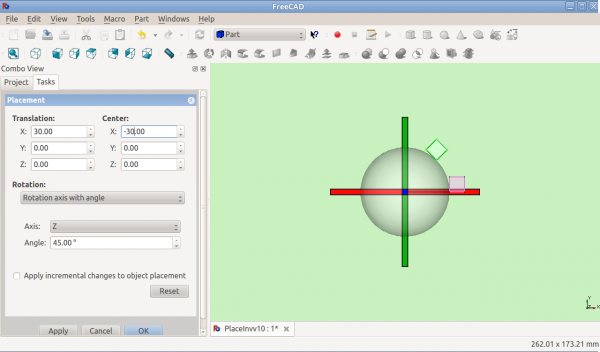
After Rotation about Z (top view)
Rotation using Euler angles:
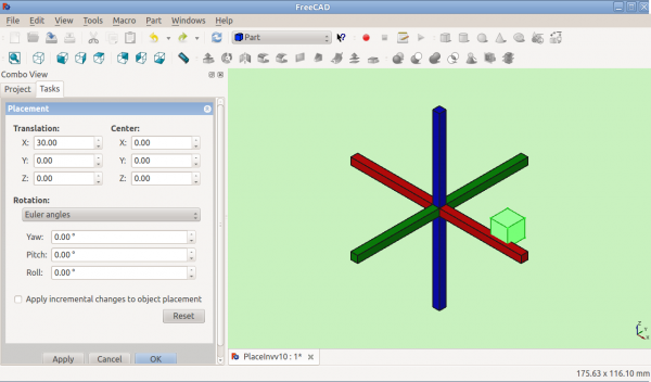
Before Rotation
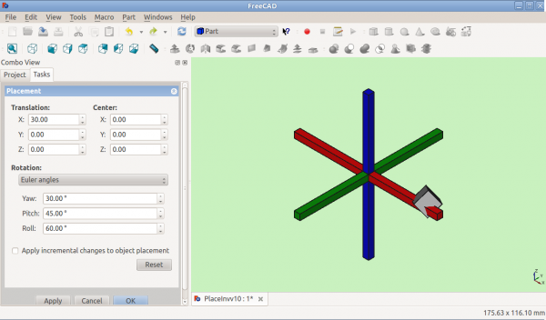
After Rotation
Placement.Base vs Shape Definition
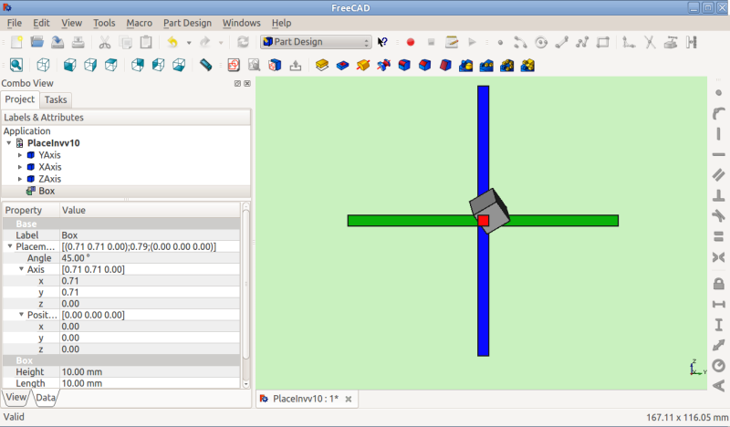
Placement is not the only way to position a shape in space. Note the Python console in this image:

Both cubes have the same value for Placement, but are in different locations! This is because the 2 shapes are defined by different vertices. For the 2 shapes in the above illustration:
 >>> ev = App.ActiveDocument.Extrude.Shape.Vertexes
 >>> for v in ev: print v.X,",",v.Y,",",v.Z
 ...
 30.0,30.0,0.0
 30.0,30.0,10.0
 40.0,30.0,0.0
 40.0,30.0,10.0
 40.0,40.0,0.0
 40.0,40.0,10.0
 30.0,40.0,0.0
 30.0,40.0,10.0
 >>> e1v = App.ActiveDocument.Extrude001.Shape.Vertexes
 >>> for v in e1v: print v.X,",",v.Y,",",v.Z
 ...
 0.0,10.0,0.0
 0.0,10.0,10.0
 10.0,10.0,0.0
 10.0,10.0,10.0
 10.0,0.0,0.0
 10.0,0.0,10.0
 0.0,0.0,0.0
 0.0,0.0,10.0
 >>>
The Vertices (or Vectors) that define the shape use the Placement.Base attribute as their origin. So if you want to move a shape 10 units along the X axis, you could add 10 to the X coordinates of all the Vertices or you could set Placement.Position to (10,0,0).
Using "Center" to Control Axis of Rotation
By default, the axis of rotation isn't really the x/y/z axis. It is a line parallel to the selected axis, but passing through the reference point (Placement.Base) of the object to be rotated. This can be changed by using the Center fields in the Placement dialog or, in scripts, by using the Center parameter of the FreeCAD.Placement constructor.
For example, suppose we have a box (below) positioned at (20,20,10).
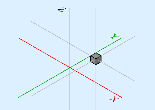
We wish to spin the box around it's own vertical centre line (ie local Z), while keeping it the same position. We can easily achieve this by specifying a Center value equal to the coordinates of the box's central point (25,25,15).

In a script, we would do:
 obj = App.ActiveDocument.Box                       # our box
 rot = FreeCAD.Rotation(FreeCAD.Vector(0,0,1),45)   # 45° about Z
 centre = FreeCAD.Vector(25,25,15)                  # central point of box
 pos = obj.Placement.Base                           # position point of box
 newplace = FreeCAD.Placement(pos,rot,centre)       # make a new Placement object
 obj.Placement = newplace                           # spin the box
Notes
- Axis and Angle can also be expressed as a quaternion.
- The reference point of an object (FreeCAD.Placement.Base) varies depending on the object. Some examples for common objects:
| Object | Reference Point |
|---|---|
| Part.Box | left (minx), front (miny), bottom (minz) vertex |
| Part.Sphere | center of the sphere (ie centre of bounding box) |
| Part.Cylinder | center of the bottom face |
| Part.Cone | center of bottom face (or apex if bottom radius is 0) |
| Part.Torus | center of the torus |
| Features derived from Sketches | the Feature inherits the Position of the underlying Sketch. Sketches always start with Position = (0,0,0). |
Issues
- As of version 0.13, update of Placement properties in the Data tab has been disabled for objects created with PartDesign, except for the initial sketch from which the solid will be created. Therefore the Placement of a solid created in PartDesign from a sketch can only be altered by adjusting Placement parameters of the initial construction sketch (the first sketch) from which the solid was created.
- Placement functionality will eventually be handled in the Assembly workbench.
More
- This tutorial: Aeroplane covers the mechanics of changing an object's Placement extensively.
- A step-by-step explanation of the Placement Dialog can be found here Tasks_Placement.
