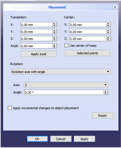
Placement
Overview
"Placement" is how FreeCAD specifies the location and attitude of an object in space. Placement can be specified in multiple forms.
Angle, Axis and Position
Placement = [Angle, Axis, Position]
Angle = r is a scalar indicating the amount of rotation of the object about Axis. Entered as degrees, but stored internally as radians.
Axis = (ax,ay,az) is a unit vector describing an axis of rotation (See Note about axis of rotation). Examples are:
   (1,0,0)       ==> about X axis
   (0,1,0)       ==> about Y axis
   (0,0,1)       ==> about Z axis
   (0.71,0.71,0) ==> about the line y=x
Position = (x,y,z) is a Vector describing the world coordinates of the reference point of the object.
Position and Yaw, Pitch and Roll

Placement = [Position, Yaw-Pitch-Roll]
Position = (x,y,z) is a Vector describing the world coordinates of the reference point of the object.
Yaw-Pitch-Roll = (y,p,r) is a tuple that specifies the attitude of the object. Values for y,p,r specify degrees of rotation about each of z,y,x. Sometimes referred to as "Euler angles". (http://en.wikipedia.org/wiki/Euler_angles)
Matrix
(see illustration of Python console) Placement = Matrix is a 4x4 affine transformation matrix (http://en.wikipedia.org/wiki/Affine_transformation) of the form:
  ((r11,r12,r13,t1),
   (r21,r22,r23,t2),
   (r31,r32,r33,t3),
   (0,0,0,1)) , with rij specifying rotation and ti specifying translation.
Placement Dialog

The Placement Dialog is invoked from the Edit menu. It is used to precisely rotate/translate objects. It is also used when we need to create a sketch on a "non standard" plane or change a sketch's orientation to a new plane.
The Apply incremental changes to object placement tick box is useful when translations/rotations are to be made relative the object's current position/attitude, rather than to the original position/attitude. .
Notes
- The axis of rotation isn't really the x/y/z axis. It is a line parallel to the selected axis, but passing through the Position point.
- The reference point of an object varies depending on the object. Some examples for common objects:
| Object | Reference Point |
|---|---|
| Part.Box | left (minx), front (miny), bottom (minz) vertex |
| Part.Sphere | centre of the sphere (ie centre of bounding box) |
| Part.Cylinder | centre of the bottom face |
| Part.Cone | centre of bottom face (or apex if bottom radius is 0) |
| Part.Torus | centre of the bounding box |
| Features derived from Sketches | the Feature inherits the Position of the underlying Sketch. Sketches always start with Position = (0,0,0). |
Issues
- As of version 0.13, update of Placement properties in the Data tab has been disabled for objects created with PartDesign. Placement functionality will eventually be handled in the Assembly workbench.