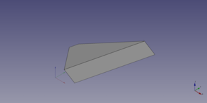
Część: Klin
|
|
| Lokalizacja w menu |
|---|
| Część → Utwórz geometrie pierwotne → Klin |
| Środowisko pracy |
| Część, OpenSCAD |
| Domyślny skrót |
| brak |
| Wprowadzono w wersji |
| - |
| Zobacz także |
| Utwórz geometrię pierwotną |
Opis
Klin środowiska praczy Część to parametryczna bryła, którą można utworzyć za pomocą polecenia
Utwórz geometrię. Ma od czterech do sześciu płaskich ścian. Jest on definiowany przez wirtualne przednie i tylne płaszczyzny główne, na których tworzona jest prostokątna ściana (domyślnie), pojedyncza prosta krawędź lub pojedynczy wierzchołek. Te kształty bazowe definiują cztery czworoboczne lub trójkątne ściany, które je łączą. Wynikowa bryła jest prawdziwym klinem tylko wtedy, gdy jeden z kształtów bazowych jest ścianą prostokątną, a drugi krawędzią prostą. W układzie współrzędnych zdefiniowanym przez właściwość DANEUmiejscowienie, wirtualne przednie i tylne główne płaszczyzny klina są równoległe do płaszczyzny XZ, a krawędzie kształtów bazowych są równoległe do osi X lub Z. Wszystkie jego współrzędne odnoszą się do tego układu współrzędnych.
Użycie
Zobacz stronę Geometrie pierwotne.
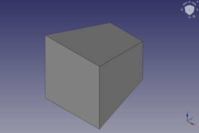
Przykład

A Part Wedge object created with the scripting example below is shown here.
Notes
- The values of the coordinates of the wedge must be such that a valid solid can be create. This means that the front and rear base shapes can both be single edges, but not if they are parallel. And if one of the base shapes is a vertex the other shape must be a rectangular face.
Properties
See also: Property editor.
A Part Wedge object is derived from a Part Feature object and inherits all its properties. It also has the following additional properties:
Data
Attachment
The object has the same attachment properties as a Part Part2DObject.
Wedge
- DANEXmin (
Distance): The lowest X coordinate of the front face of the wedge. The default is0mm. - DANEYmin (
Distance): The Y coordinate of the front face of the wedge. The default is0mm. - DANEZmin (
Distance): The lowest Z coordinate of the front face of the wedge. The default is0mm. - DANEX2min (
Distance): The lowest X coordinate of the rear face of the wedge. The default is2mm. - DANEZ2min (
Distance): The lowest Z coordinate of the rear face of the wedge. The default is2mm. - DANEXmax (
Distance): The highest X coordinate of the front face of the wedge. The default is10mm. - DANEYmax (
Distance): The Y coordinate of the rear face of the wedge. The default is10mm. - DANEZmax (
Distance): The highest Z coordinate of the front face of the wedge. The default is10mm. - DANEX2max (
Distance): The highest X coordinate of the rear face of the wedge. The default is8mm. - DANEZ2max (
Distance): The highest Z coordinate of the rear face of the wedge. The default is8mm.
Scripting
See also: Autogenerated API documentation, Part scripting and FreeCAD Scripting Basics.
A Part Wedge can be created with the addObject() method of the document:
wedge = FreeCAD.ActiveDocument.addObject("Part::Wedge", "myWedge")
- Where
"myWedge"is the name for the object. - The function returns the newly created object.
Example:
import FreeCAD as App

doc = App.activeDocument()

wedge = doc.addObject("Part::Wedge", "myWedge")
wedge.Xmin = 1
wedge.Ymin = 2
wedge.Zmin = 3
wedge.X2min = 4
wedge.Z2min = 6
wedge.Xmax = 15
wedge.Ymax = 20
wedge.Zmax = 55
wedge.X2max = 10
wedge.Z2max = 12
wedge.Placement = App.Placement(App.Vector(1, 2, 3), App.Rotation(75, 60, 30))

doc.recompute()
- Bryły pierwotne: Prostopadłościan, Walec, Sfera, Stożek, Torus, Rura, Bryły pierwotne, Konstruktor kształtu
- Tworzenie i modyfikacja: Wyciągnij, Wyciągnij przez obrót, Odbicie lustrzane, Zaokrąglenie, Fazka, Utwórz ścianę z linii łamanych, Powierzchnia prostokreślna, Wyciągnięcie przez profile, Wyciągnięcie po ścieżce, Przecięcie, Przekrój poprzeczny, Odsunięcie 3D, Odsunięcie 2D, Grubość, Rzutowanie na powierzchnię, Mocowanie
- Funkcje logiczne: Utwórz złożenie, Rozbij złożenie, Filtr złożeń, Funkcje logiczne, Wytnij, Połączenie, Część wspólna, Przyłącz, Dołącz do osadzenia, Wycięcie połączenia, Funkcja logiczna rozdzielająca, Pokrój część, Krojenie, XOR
- Wymiarowanie: Wymiarowanie liniowe, Wymiarowanie kątowe, Odśwież wymiary, Usuń wymiary, Przełącz widoczność wymiaru, Przełącz widoczność wymiarów przestrzennych, Przełącz widoczność wymiarów przyrostowych
- Jak zacząć
- Instalacja: Pobieranie programu, Windows, Linux, Mac, Dodatkowych komponentów, Docker, AppImage, Ubuntu Snap
- Podstawy: Informacje na temat FreeCAD, Interfejs użytkownika, Profil nawigacji myszką, Metody wyboru, Nazwa obiektu, Edytor ustawień, Środowiska pracy, Struktura dokumentu, Właściwości, Pomóż w rozwoju FreeCAD, Dotacje
- Pomoc: Poradniki, Wideo poradniki
- Środowiska pracy: Strona Startowa, Architektura, Assembly, CAM, Rysunek Roboczy, MES, Inspekcja, Siatka, OpenSCAD, Część, Projekt Części, Punkty, Inżynieria Wsteczna, Robot, Szkicownik, Arkusz Kalkulacyjny, Powierzchnia 3D, Rysunek Techniczny, Test Framework
