Part Plane: Difference between revisions
m (→Scripting) |
(Marked this version for translation) |
||
| (22 intermediate revisions by 2 users not shown) | |||
| Line 1: | Line 1: | ||
<languages/> |
<languages/> |
||
{{UnfinishedDocu{{#translation:}}}} <!-- Note: Needs Usage section with ordered list. --> |
|||
<translate> |
<translate> |
||
| Line 17: | Line 16: | ||
|Name=Part Plane |
|Name=Part Plane |
||
|MenuLocation=Part → [[Part_Primitives|Create primitives]] → Plane |
|MenuLocation=Part → [[Part_Primitives|Create primitives]] → Plane |
||
|Workbenches=[[Part_Workbench|Part]] |
|Workbenches=[[Part_Workbench|Part]], [[OpenSCAD_Workbench|OpenSCAD]] |
||
|SeeAlso=[[Part_Primitives|Part Primitives]] |
|SeeAlso=[[Part_Primitives|Part Primitives]] |
||
}} |
}} |
||
| Line 24: | Line 23: | ||
<!--T:7--> |
<!--T:7--> |
||
A [[Image:Part_Plane.svg|24px]] '''Part Plane''' is a parametric rectangular plane that can be created with the [[Image:Part_Primitives.svg|24px]] [[Part_Primitives|Part Primitives]] command. In the coordinate system defined by its {{PropertyData|Placement}} property, the plane lies on the XY plane with its front left corner at the origin, and its front edge parallel to the X axis. |
|||
Create a simple parametric plane 10 x 10 mm, with the parameters of position, length, and width. |
|||
By default, the plane is positioned at the origin (0,0,0). |
|||
</translate> |
</translate> |
||
[[Image:Part_Plane_Example.png|400px]] |
|||
[[File:Part Plane Example.png|Screenshot of the Part Plane with default values]] |
|||
<translate> |
<translate> |
||
== Usage == <!--T:8--> |
== Usage == <!--T:8--> |
||
<!--T: |
<!--T:24--> |
||
See [[Part_Primitives#Usage|Part Primitives]]. |
|||
The standard plane is created with its lower left corner at the origin point {{incode|0,0,0}}. |
|||
To change these parameters, open the Location section and enter the desired values in the respective input fields, or click on the [[3D_view|3D view]] and select a point, the point coordinates are taken from the fields. |
|||
In the Direction menu you can also define a standard vector (X, Y or Z) normal to the plane, or click User Defined ... to open the dialog box that allows you to set a different carrier (eg. direction 1.0 , -1 creates a plane inclined 45° with respect to X and Z). |
|||
<!--T: |
== Example == <!--T:25--> |
||
The properties of the object can be edited, either in the [[Property_editor|Property editor]] or by double-clicking the object in the [[Tree_view|Tree view]]. |
|||
| ⚫ | |||
[[Image:Part_Plane_Scripting_Example.png|thumb|Part Plane from the scripting example]] |
|||
| ⚫ | |||
A Part Plane object created with the [[#Scripting|scripting example]] below is shown here. |
|||
== Properties == <!--T:16--> |
== Properties == <!--T:16--> |
||
<!--T:28--> |
|||
See also: [[Property_editor|Property editor]]. |
|||
<!--T:29--> |
|||
A Part Plane object is derived from a [[Part_Feature|Part Feature]] object and inherits all its properties. It also has the following additional properties: |
|||
=== Data === <!--T:17--> |
=== Data === <!--T:17--> |
||
<!--T: |
<!--T:30--> |
||
{{TitleProperty| |
{{TitleProperty|Attachment}} |
||
<!--T: |
<!--T:31--> |
||
The object has the same attachment properties as a [[Part_Part2DObject#Data|Part Part2DObject]]. |
|||
* {{PropertyData|Placement|Placement}}: Placement of feature is defined by below angle, axis and position. |
|||
** {{PropertyData|Angle|Angle}}: Angle of rotation relative to the below axis. |
|||
** {{PropertyData|Axis}}: Defines the axis of rotation plane: X, Y, or Z. Defaults to Z axis, Z = 1 |
|||
** {{PropertyData|Position}}: Position X, Y, Z, relative to the origin 0, 0, 0. |
|||
* {{PropertyData|Label|String}}: String name of the object, defaults to 'Plane'. User may rename it. |
|||
<!--T:20--> |
<!--T:20--> |
||
| Line 59: | Line 62: | ||
<!--T:21--> |
<!--T:21--> |
||
* {{PropertyData|Length|Length}}: |
* {{PropertyData|Length|Length}}: The length of the plane. This is the dimension in its X direction. The default is {{Value|10mm}}. |
||
* {{PropertyData|Width|Length}}: |
* {{PropertyData|Width|Length}}: The width of the plane. This is the dimension in its Y direction. The default is {{Value|10mm}}. |
||
== Scripting == <!--T:32--> |
|||
<!--T: |
<!--T:33--> |
||
See also: [https://freecad.github.io/SourceDoc/ Autogenerated API documentation], [[Part_scripting|Part scripting]] and [[FreeCAD_Scripting_Basics|FreeCAD Scripting Basics]]. |
|||
You have the standard properties view. |
|||
<!--T:34--> |
|||
| ⚫ | |||
==Notes== |
|||
==Properties== |
|||
==Limitations== |
|||
==Scripting== |
|||
| ⚫ | |||
</translate> |
</translate> |
||
| Line 84: | Line 79: | ||
<translate> |
<translate> |
||
<!--T: |
<!--T:35--> |
||
* Where {{Incode|myPlane}} is the name for the object |
* Where {{Incode|"myPlane"}} is the name for the object. |
||
* The function returns the newly created object. |
* The function returns the newly created object. |
||
<!--T:36--> |
|||
The {{Incode|Label}} is the user editable name for the object. It can be easily changed by |
|||
Example: |
|||
</translate> |
</translate> |
||
{{Code|code= |
{{Code|code= |
||
import FreeCAD as App |
|||
plane.Label = "new myPlaneName" |
|||
}} |
|||
<translate> |
|||
doc = App.activeDocument() |
|||
| ⚫ | |||
You can access and modify attributes of the {{Incode|plane}} object. For example, you may wish to modify the length and width parameters. |
|||
plane = doc.addObject("Part::Plane", "myPlane") |
|||
</translate> |
|||
{{Code|code= |
|||
plane.Length = 4 |
plane.Length = 4 |
||
plane.Width = 8 |
plane.Width = 8 |
||
| ⚫ | |||
}} |
|||
<translate> |
|||
doc.recompute() |
|||
| ⚫ | |||
You can change its placement with: |
|||
</translate> |
|||
{{Code|code= |
|||
| ⚫ | |||
}} |
}} |
||
<translate> |
<translate> |
||
| Line 127: | Line 113: | ||
</translate> |
</translate> |
||
{{ |
{{Part_Tools_navi{{#translation:}}}} |
||
{{Userdocnavi{{#translation:}}}} |
{{Userdocnavi{{#translation:}}}} |
||
Latest revision as of 10:03, 3 March 2022
|
|
| Menu location |
|---|
| Part → Create primitives → Plane |
| Workbenches |
| Part, OpenSCAD |
| Default shortcut |
| None |
| Introduced in version |
| - |
| See also |
| Part Primitives |
Description
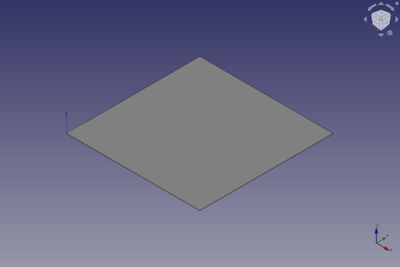
A Part Plane is a parametric rectangular plane that can be created with the
Part Primitives command. In the coordinate system defined by its DataPlacement property, the plane lies on the XY plane with its front left corner at the origin, and its front edge parallel to the X axis.
Usage
See Part Primitives.
Example

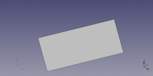
A Part Plane object created with the scripting example below is shown here.
Properties
See also: Property editor.
A Part Plane object is derived from a Part Feature object and inherits all its properties. It also has the following additional properties:
Data
Attachment
The object has the same attachment properties as a Part Part2DObject.
Plane
- DataLength (
Length): The length of the plane. This is the dimension in its X direction. The default is10mm. - DataWidth (
Length): The width of the plane. This is the dimension in its Y direction. The default is10mm.
Scripting
See also: Autogenerated API documentation, Part scripting and FreeCAD Scripting Basics.
A Part Plane can be created with the addObject() method of the document:
plane = FreeCAD.ActiveDocument.addObject("Part::Plane", "myPlane")
- Where
"myPlane"is the name for the object. - The function returns the newly created object.
Example:
import FreeCAD as App

doc = App.activeDocument()

plane = doc.addObject("Part::Plane", "myPlane")
plane.Length = 4
plane.Width = 8
plane.Placement = App.Placement(App.Vector(1, 2, 3), App.Rotation(20, 75, 60))

doc.recompute()
- Primitives: Box, Cylinder, Sphere, Cone, Torus, Tube, Create primitives, Shape builder
- Creation and modification: Extrude, Revolve, Mirror, Fillet, Chamfer, Make face from wires, Ruled Surface, Loft, Sweep, Section, Cross sections, 3D Offset, 2D Offset, Thickness, Projection on surface, Attachment
- Boolean: Make compound, Explode Compound, Compound Filter, Boolean, Cut, Fuse, Common, Connect, Embed, Cutout, Boolean fragments, Slice apart, Slice, XOR
- Measure: Measure Linear, Measure Angular, Measure Refresh, Clear All, Toggle All, Toggle 3D, Toggle Delta
- Getting started
- Installation: Download, Windows, Linux, Mac, Additional components, Docker, AppImage, Ubuntu Snap
- Basics: About FreeCAD, Interface, Mouse navigation, Selection methods, Object name, Preferences, Workbenches, Document structure, Properties, Help FreeCAD, Donate
- Help: Tutorials, Video tutorials
- Workbenches: Std Base, Arch, Assembly, CAM, Draft, FEM, Inspection, Mesh, OpenSCAD, Part, PartDesign, Points, Reverse Engineering, Robot, Sketcher, Spreadsheet, Surface, TechDraw, Test Framework
- Hubs: User hub, Power users hub, Developer hub
