Part Builder: Difference between revisions
(→Face from edges: add image) |
Tag: Undo |
||
| (8 intermediate revisions by 3 users not shown) | |||
| Line 1: | Line 1: | ||
<languages/> |
<languages/> |
||
<translate> |
<translate> |
||
<!--T:6--> |
<!--T:6--> |
||
{{Docnav |
{{Docnav |
||
|[[Part_RegularPolygon|RegularPolygon]] |
|[[Part_RegularPolygon|RegularPolygon]] |
||
|[[Part_Extrude|Extrude]] |
|[[Part_Extrude|Extrude]] |
||
|[[ |
|[[Part_Workbench|Part]] |
||
|IconL=Part_RegularPolygon.svg |
|IconL=Part_RegularPolygon.svg |
||
|IconR=Part_Extrude.svg |
|IconR=Part_Extrude.svg |
||
| Line 15: | Line 16: | ||
|Name=Part Builder |
|Name=Part Builder |
||
|MenuLocation=Part → Shape builder... |
|MenuLocation=Part → Shape builder... |
||
|Workbenches=[[ |
|Workbenches=[[Part_Workbench|Part]] |
||
|SeeAlso=[[Part_Primitives|Part Primitives]] |
|SeeAlso=[[Part_Primitives|Part Primitives]] |
||
}} |
}} |
||
==Description== <!--T: |
==Description== <!--T:22--> |
||
<!--T:2--> |
|||
A tool to create more complex shapes from various parametric geometric primitives. |
A tool to create more complex shapes from various parametric geometric primitives. |
||
==Usage== <!--T:3--> |
==Usage== <!--T:3--> |
||
<!--T:8--> |
|||
This tool will let you create shapes by through several optional choices: |
|||
This tool can create the following objects: |
|||
===Edge from two vertices=== |
===Edge from two vertices=== <!--T:9--> |
||
<!--T:10--> |
|||
#Select two vertices |
#Select two vertices |
||
#Click on {{Button|Create}} |
#Click on {{Button|Create}} |
||
[[Image:Edge from verts-1.gif]] |
[[Image:Edge from verts-1.gif]] |
||
===Wire from edges=== |
===Wire from edges=== <!--T:11--> |
||
{{Version|0.18}} |
|||
<!--T:13--> |
|||
#Select a set of adjacent edges in the [[3D_view|3D view]] |
#Select a set of adjacent edges in the [[3D_view|3D view]] |
||
#Click on {{Button|Create}} |
#Click on {{Button|Create}} |
||
[[File:Wire_from_edges-1.gif]] |
[[File:Wire_from_edges-1.gif]] |
||
===Face from vertices=== |
===Face from vertices=== <!--T:14--> |
||
<!--T:15--> |
|||
#Select vertices bounding the face in the [[3D_view|3D view]] |
#Select vertices bounding the face in the [[3D_view|3D view]] |
||
#Select if face should be planar |
#Select if face should be planar |
||
| Line 48: | Line 53: | ||
[[File:Face_from_verts.gif]] |
[[File:Face_from_verts.gif]] |
||
===Face from edges=== |
===Face from edges=== <!--T:16--> |
||
<!--T:17--> |
|||
#Select a closed set of edges bounding the face in the [[3D_view|3D view]] |
#Select a closed set of edges bounding the face in the [[3D_view|3D view]] |
||
#Select if face should be planar |
#Select if face should be planar |
||
| Line 56: | Line 62: | ||
[[File:Face_from_edges.gif]] |
[[File:Face_from_edges.gif]] |
||
===Shell from faces=== |
===Shell from faces=== <!--T:18--> |
||
<!--T:19--> |
|||
#Select faces in the [[3D_view|3D view]] |
#Select faces in the [[3D_view|3D view]] |
||
#Select if the shape should be refined |
#Select if the shape should be refined |
||
| Line 64: | Line 71: | ||
#Object will be created in [[3D_view|3D view]] and will be listed in [[Tree_view|tree view]] |
#Object will be created in [[3D_view|3D view]] and will be listed in [[Tree_view|tree view]] |
||
===Solid from shell=== |
===Solid from shell=== <!--T:20--> |
||
<!--T:21--> |
|||
#Select if the shape should be refined |
#Select if the shape should be refined |
||
#Click on {{Button|Create}} |
#Click on {{Button|Create}} |
||
#Object will be created in [[3D_view|3D view]] and will be listed in [[Tree_view|tree view]] |
#Object will be created in [[3D_view|3D view]] and will be listed in [[Tree_view|tree view]] |
||
== |
==Notes== <!--T:23--> |
||
<br /> |
|||
<!--T:5--> |
|||
A possible workflow could be: |
A possible workflow could be: |
||
*Draw a wireframe-model of your shape using the tools in the [[Image:Workbench_Draft.svg|24px]] [[Draft_Workbench|Draft Workbench]] (for example line and dwire) |
* Draw a wireframe-model of your shape using the tools in the [[Image:Workbench_Draft.svg|24px]] [[Draft_Workbench|Draft Workbench]] (for example line and dwire) |
||
*Create all faces with "face from edges" |
* Create all faces with "face from edges" |
||
*Create a "shell from faces" |
* Create a "shell from faces" |
||
*Create a "solid from shell" |
* Create a "solid from shell" |
||
| Line 85: | Line 92: | ||
|[[Part_RegularPolygon|RegularPolygon]] |
|[[Part_RegularPolygon|RegularPolygon]] |
||
|[[Part_Extrude|Extrude]] |
|[[Part_Extrude|Extrude]] |
||
|[[ |
|[[Part_Workbench|Part]] |
||
|IconL=Part_RegularPolygon.svg |
|IconL=Part_RegularPolygon.svg |
||
|IconR=Part_Extrude.svg |
|IconR=Part_Extrude.svg |
||
| Line 94: | Line 101: | ||
{{Part Tools navi{{#translation:}}}} |
{{Part Tools navi{{#translation:}}}} |
||
{{Userdocnavi{{#translation:}}}} |
{{Userdocnavi{{#translation:}}}} |
||
{{clear}} |
|||
Latest revision as of 12:11, 21 January 2023
|
|
| Menu location |
|---|
| Part → Shape builder... |
| Workbenches |
| Part |
| Default shortcut |
| None |
| Introduced in version |
| - |
| See also |
| Part Primitives |
Description
A tool to create more complex shapes from various parametric geometric primitives.
Usage
This tool can create the following objects:
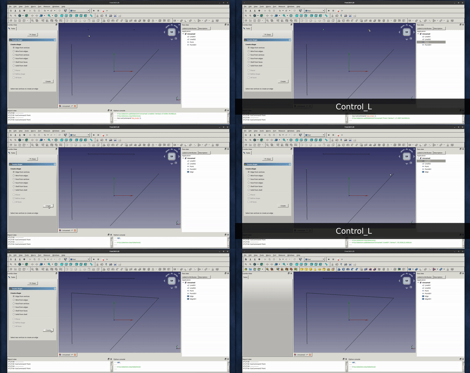
Edge from two vertices
- Select two vertices
- Click on Create
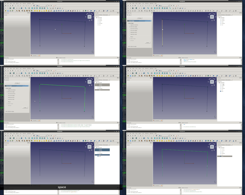
Wire from edges
- Select a set of adjacent edges in the 3D view
- Click on Create
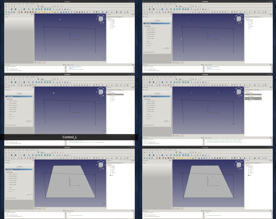
Face from vertices
- Select vertices bounding the face in the 3D view
- Select if face should be planar
- Click on Create
- Object will be created in 3D view and will be listed in tree view
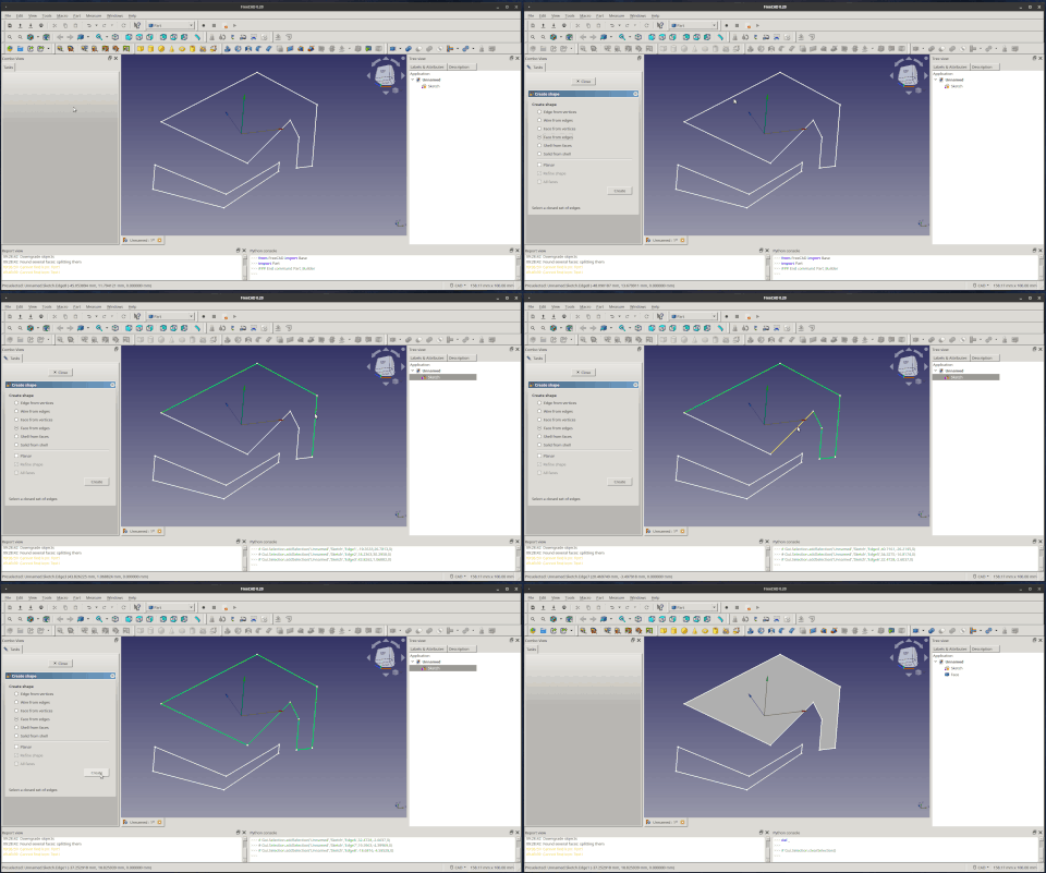
Face from edges
- Select a closed set of edges bounding the face in the 3D view
- Select if face should be planar
- Click on Create
- Object will be created in 3D view and will be listed in tree view
Shell from faces
- Select faces in the 3D view
- Select if the shape should be refined
- Select if all faces should be included in shell
- Click on Create
- Object will be created in 3D view and will be listed in tree view
Solid from shell
- Select if the shape should be refined
- Click on Create
- Object will be created in 3D view and will be listed in tree view
Notes
A possible workflow could be:
- Draw a wireframe-model of your shape using the tools in the
Draft Workbench (for example line and dwire)
- Create all faces with "face from edges"
- Create a "shell from faces"
- Create a "solid from shell"
- Primitives: Box, Cylinder, Sphere, Cone, Torus, Tube, Create primitives, Shape builder
- Creation and modification: Extrude, Revolve, Mirror, Fillet, Chamfer, Make face from wires, Ruled Surface, Loft, Sweep, Section, Cross sections, 3D Offset, 2D Offset, Thickness, Projection on surface, Attachment
- Boolean: Make compound, Explode Compound, Compound Filter, Boolean, Cut, Fuse, Common, Connect, Embed, Cutout, Boolean fragments, Slice apart, Slice, XOR
- Measure: Measure Linear, Measure Angular, Measure Refresh, Clear All, Toggle All, Toggle 3D, Toggle Delta
- Getting started
- Installation: Download, Windows, Linux, Mac, Additional components, Docker, AppImage, Ubuntu Snap
- Basics: About FreeCAD, Interface, Mouse navigation, Selection methods, Object name, Preferences, Workbenches, Document structure, Properties, Help FreeCAD, Donate
- Help: Tutorials, Video tutorials
- Workbenches: Std Base, Arch, Assembly, CAM, Draft, FEM, Inspection, Mesh, OpenSCAD, Part, PartDesign, Points, Reverse Engineering, Robot, Sketcher, Spreadsheet, Surface, TechDraw, Test Framework
- Hubs: User hub, Power users hub, Developer hub


