PartDesign PolarPattern/es: Difference between revisions
(Updating to match new version of source page) |
(Updating to match new version of source page) |
||
| Line 1: | Line 1: | ||
<languages/> |
<languages/> |
||
{{Docnav |
|||
{{Docnav|[[PartDesign_LinearPattern|Linear Pattern]]|[[PartDesign_MultiTransform|Create MultiTransform]]|[[PartDesign_Workbench|PartDesign]]|IconL=PartDesign_LinearPattern.png|IconC=Workbench_PartDesign.svg|IconR=PartDesign_MultiTransform.png}} |
|||
|[[PartDesign_LinearPattern|Linear Pattern]] |
|||
|[[PartDesign_MultiTransform|Create MultiTransform]] |
|||
|[[PartDesign_Workbench|PartDesign]] |
|||
|IconL=PartDesign_LinearPattern.svg |
|||
|IconC=Workbench_PartDesign.svg |
|||
|IconR=PartDesign_MultiTransform.svg |
|||
}} |
|||
{{GuiCommand/es |
{{GuiCommand/es |
||
| Line 21: | Line 28: | ||
# Select the feature(s) to be patterned. Alternatively, the feature can be selected from a dialogue after step 2. |
# Select the feature(s) to be patterned. Alternatively, the feature can be selected from a dialogue after step 2. |
||
#: |
#: {{VersionMinus|0.16}} Only a single feature can be selected, and it must be the last one at the bottom of the feature tree. |
||
# Press the {{KEY|[[File: |
# Press the {{KEY|[[File:PartDesign_PolarPattern.svg|24px]]}} '''PolarPattern''' button. |
||
# |
# {{VersionPlus|0.17}} Press {{KEY|Add feature}} to add a feature to be patterned. The feature must be visible in the 3D view: |
||
## Switch to the Model tree; |
## Switch to the Model tree; |
||
## Select in the tree the feature to be added and press {{KEY| |
## Select in the tree the feature to be added and press {{KEY|Spacebar}} to make it visible in the 3D view; |
||
## Switch back to the Tasks panel; |
## Switch back to the Tasks panel; |
||
## Select the feature in the 3D view; it will be added to the list. |
## Select the feature in the 3D view; it will be added to the list. |
||
## Repeat to add other features. |
## Repeat to add other features. |
||
# |
# {{VersionPlus|0.17}} Press {{KEY|Remove feature}} to remove a feature from the list, or right-click on the feature in the list and select ''Remove''. |
||
# Define the axis. See [[#Options|Options]]. |
# Define the axis. See [[#Options|Options]]. |
||
# Define the angle between the last copied occurrence and the original feature. |
# Define the angle between the last copied occurrence and the original feature. |
||
| Line 61: | Line 68: | ||
====Eje (X/Y/Z) base==== |
====Eje (X/Y/Z) base==== |
||
{{VersionPlus|0.17}} Select one of the Body Origin's standard axis (X, Y or Z) as axis. |
|||
====Seleccione referencia...==== |
====Seleccione referencia...==== |
||
| Line 76: | Line 83: | ||
{{clear}} |
{{clear}} |
||
{{Docnav |
|||
{{Docnav|[[PartDesign_LinearPattern|Linear Pattern]]|[[PartDesign_MultiTransform|Create MultiTransform]]|[[PartDesign_Workbench|PartDesign]]|IconL=PartDesign_LinearPattern.png|IconC=Workbench_PartDesign.svg|IconR=PartDesign_MultiTransform.png}} |
|||
|[[PartDesign_LinearPattern|Linear Pattern]] |
|||
|[[PartDesign_MultiTransform|Create MultiTransform]] |
|||
|[[PartDesign_Workbench|PartDesign]] |
|||
|IconL=PartDesign_LinearPattern.svg |
|||
|IconC=Workbench_PartDesign.svg |
|||
|IconR=PartDesign_MultiTransform.svg |
|||
}} |
|||
{{PartDesign Tools navi}} |
{{PartDesign Tools navi{{#translation:}}}} |
||
| ⚫ | |||
| ⚫ | |||
Revision as of 02:21, 24 February 2020
|
|
| Ubicación en el Menú |
|---|
| Part Design → Patrón polar |
| Entornos de trabajo |
| PartDesign |
| Atajo de teclado por defecto |
| Ninguno |
| Introducido en versión |
| - |
| Ver también |
| Ninguno |
Descripción
La herramienta 'patrón polar' toma una función seleccionada y crea un conjunto de copias giradas alrededor de un eje elegido. A partir de v0.17, puede crear múltiples funciones.

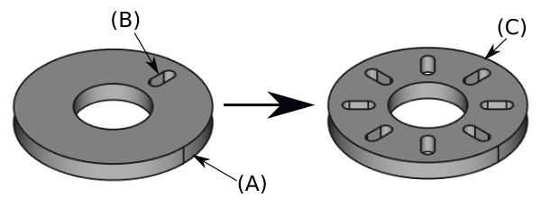
Above: a slot-shaped pocket (B) made on top of a base solid (A, also referred to as support) is used for a polar pattern. The result (C) is shown on the right.
Utilización
- Select the feature(s) to be patterned. Alternatively, the feature can be selected from a dialogue after step 2.
- version 0.16 and below Only a single feature can be selected, and it must be the last one at the bottom of the feature tree.
- Press the
PolarPattern button.
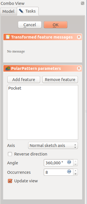
- version 0.17 and above Press Add feature to add a feature to be patterned. The feature must be visible in the 3D view:
- Switch to the Model tree;
- Select in the tree the feature to be added and press Spacebar to make it visible in the 3D view;
- Switch back to the Tasks panel;
- Select the feature in the 3D view; it will be added to the list.
- Repeat to add other features.
- version 0.17 and above Press Remove feature to remove a feature from the list, or right-click on the feature in the list and select Remove.
- Define the axis. See Options.
- Define the angle between the last copied occurrence and the original feature.
- Set the number of occurrences.
- Press OK.
Opciones

Eje
Cuando se crea una operación de matriz polar, el letrero de diálogo de 'parámetros de matriz polar' ofrece modos diferentes de especificar el eje de rotación de la matriz.
Normal sketch axis
An axis being normal to the sketch and starting in the origin of the sketch of the feature being used is taken as axis for the polar pattern.
The pattern direction can be reversed by ticking 'Reverse direction'.
Eje horizontal del croquis
Uses the horizontal axis of the sketch for axis.
Eje vertical del croquis
Uses the vertical axis of the sketch for axis.
Custom Sketch Axis
If the sketch which defines the feature to be patterned also contains a construction line (or lines), then the drop down list will contain one custom sketch axis for each construction line. The first construction line will be labelled Sketch axis 0.
Eje (X/Y/Z) base
version 0.17 and above Select one of the Body Origin's standard axis (X, Y or Z) as axis.
Seleccione referencia...
Allows you to select either a DatumLine or an edge of an object or a line of a sketch to use for axis.
Ángulo y instancias
Especifica el ángulo que cubrirá la matriz, y el número total de formas del patrón (incluida la operación original). Por ejemplo, cuatro instancias en un ángulo de 180 grados debería espaciar las formas de la matriz 60 grados entre si. Existe una excepción: Si el ángulo es de 360 grados, ya que la primera y última instancia son idénticas, se espaciarán cuatro instancias a 90 grados entre si.
Limitaciones
- Structure tools: Part, Group
- Helper tools: Create body, Create sketch, Edit sketch, Map sketch to face
- Modeling tools
- Datum tools: Create a datum point, Create a datum line, Create a datum plane, Create a local coordinate system, Create a shape binder, Create a sub-object(s) shape binder, Create a clone
- Additive tools: Pad, Revolution, Additive loft, Additive pipe, Additive helix, Additive box, Additive cylinder, Additive sphere, Additive cone, Additive ellipsoid, Additive torus, Additive prism, Additive wedge
- Subtractive tools: Pocket, Hole, Groove, Subtractive loft, Subtractive pipe, Subtractive helix, Subtractive box, Subtractive cylinder, Subtractive sphere, Subtractive cone, Subtractive ellipsoid, Subtractive torus, Subtractive prism, Subtractive wedge
- Transformation tools: Mirrored, Linear Pattern, Polar Pattern, Create MultiTransform, Scaled
- Dress-up tools: Fillet, Chamfer, Draft, Thickness
- Boolean: Boolean operation
- Extras: Migrate, Sprocket, Involute gear, Shaft design wizard
- Context menu: Set tip, Move object to other body, Move object after other object, Appearance, Color per face
- Getting started
- Installation: Download, Windows, Linux, Mac, Additional components, Docker, AppImage, Ubuntu Snap
- Basics: About FreeCAD, Interface, Mouse navigation, Selection methods, Object name, Preferences, Workbenches, Document structure, Properties, Help FreeCAD, Donate
- Help: Tutorials, Video tutorials
- Workbenches: Std Base, Arch, Assembly, CAM, Draft, FEM, Inspection, Mesh, OpenSCAD, Part, PartDesign, Points, Reverse Engineering, Robot, Sketcher, Spreadsheet, Surface, TechDraw, Test Framework
- Hubs: User hub, Power users hub, Developer hub