PartDesign Pad
|
|
| Menu location |
|---|
| PartDesign -> Pad |
| Workbenches |
| PartDesign, Complete |
| Default shortcut |
| None |
| Introduced in version |
| - |
| See also |
| None |
Introduction
'Pad a selected sketch' - This tool takes a selected sketch as its input (the 'defining sketch'), and produces with it a 'pad'. A pad is essentially an extrusion of a sketch. For example, if a sketch were made of two concentric circles, and the pad tool were subsequently used on this sketch, the result would be a cylinder:

Options

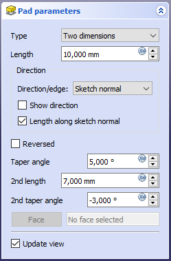
When creating a pad, the 'pad parameters' dialogue offers five different ways of specifying the length to which the pad will be extruded:
Dimension
Enter a numeric value for the length of the pad. The default direction for extrusion is away (outside of) the sketch support.
Length
This parameter sets the length a sketch is to be extruded by. Extrusions occur normal to the defining sketch plane.
Mirrored extent
This parameter is not currently implemented - the intention is to allow a mirroring of the pad about the plane of its defining sketch.
Reverse
A switch to toggle the direction of the extrusion (positive or negative along the normal of its defining sketch). (Default = False).