入門
新特性
- 0.17版發佈公告 : 查看0.17版Freecad的新特性
- 0.16版發佈公告 : 查看0.16版Freecad的新特性
- 0.15版發佈公告 : 查看0.15版Freecad的新特性
- 0.14版發佈公告 : 查看0.14版Freecad的新特性
- 0.13版發佈公告 : 查看0.13版Freecad的新特性
- 0.12版發佈公告 : 查看0.12版Freecad的新特性
- 0.11版發佈公告 : 查看0.11版Freecad的新特性
前言
FreeCAD是一種3D CAD/CAE參數化建模程序.它主要用於機械設計但是同樣可以用於其他需要精確建模3D對象以及控制建模記錄的設計工作。
到目前為止,FreeCAD已經處於開發狀態有些時日了,它為你提供很多設計功能。 和商業解決方案相比較,它仍有一些功能缺失,而且可能不足以用於許多生產環境,但對於多數業餘愛好者和許多小型工廠來說它足夠強大。這裏有一個快速增長的熱心用戶社區,他們都加入了FreeCAD論壇,同時你也能夠在論壇里找到許多在開發過程中使用FreeCAD的高品質項目案例
像所有開源項目,FreeCAD項目不是一個開發人員向你傳遞結果的一個單向工作,它更多依靠它的社區的成長、獲得新的功能以及使其變得穩定(缺陷修正)。所以在使用FreeCAD的時候不要忘記,如果你願意,你可以直接影響並且幫助FreeCAD!
安裝
首先,下載並安裝FreeCAD。參見下載頁面獲取更多當前版本信息以及更新信息,並在安裝頁面查看安裝指導。FreeCAD支持Windows(.msi),Debian和Ubuntu (.deb), openSUSE (.rpm)以及Mac OSX環境,也可以通過許多Linux發行版的安裝包管理器獲取並安裝,同時還有可以在最新64位Linux系統上運行的獨立AppImage可執行文件。因為FreeCAD是開源軟件,你也可以獲取原始碼並且自己對其進行編譯。
探索FreeCAD
- 3D視圖,顯示你的文檔
- 樹狀視圖, 顯示你的文檔中所有對象的層次結構記錄。
- 屬性編輯器,允許你瀏覽和修改選定對象的屬性
- 報告視圖(或者輸出視圖),FreeCAD打印信息、警告和錯誤的地方
- Python控制台,所有FreeCAD執行的命令將在這裏打印出來,你也可以在這裏輸入和執行Python代碼
- 工作枱選擇器, 用於選擇並激活不同的工作枱。
FreeCAD界面背後的主要概念是它被分成 工作枱.一個工作枱是一批適用於特定任務的工具的集合,比如使用網格、繪製2D對象、 帶約束的草圖. 你可以通過工作枱選擇器(6)切換當前工作枱.你可以定製在每個工作枱中包含的工具、添加其他工作枱的工具甚至自己創建工具(我們稱之為宏命令)。被廣泛使用的設計工作起始點是零件設計工作枱 和零件工作枱.
當你啟動FreeCAD的時候,你將會看到啟動中心。下面你看到的是0.16版的啟動中心:
FreeCAD 0.17版見啟動中心截屏.
啟動中心使你可以快速跳轉到常用的工作枱,打開最近編輯過的文件或者查看來自FreeCAD世界最近的新聞。你可以在FreeCAD主程序的參考中按照自己的需要改變啟動中心的默認工作枱。
在3D設計空間中的操作
FreeCAD有許多不同的鼠標操控模式可用, 選擇不同的操控模式會改變你使用鼠標操控3D視圖中對象和改變3D視圖方式。操控模式有一個是特別為觸控板設計的觸控板, 該模式下鼠標中鍵不可用. 下列表格中描述了默認操控模式,叫做CAD操作 (你可以通過在3D視圖的空白處右鍵單擊跳出的菜單中進行選擇以迅速改變當前操控:
| 選擇 | 移動 | 縮放 | 旋轉視圖 第一種方法 |
旋轉視圖 其他方法 |
|---|---|---|---|---|

|

|

|

|

|
| 選擇單個對象:在你想要選取的目標上方按下鼠標左鍵。
選擇多個對象:按下Ctrl的同時逐個在你需要選取的對象的上方按下鼠標左鍵。 |
Hold the middle mouse button, then move the pointer. | Use the mouse wheel to zoom in and out.
Clicking the middle mouse button re-centers the view on the location of the cursor. |
Hold the middle mouse button, then press and hold the left mouse button, then move the pointer.
The cursor location when the middle mouse button is pressed determines the center of rotation. Rotation works like spinning a ball which rotates around its center. If the buttons are released before you stop the mouse motion, the view continues spinning, if this is enabled. A double click with the middle mouse button sets a new center of rotation. |
Hold the middle mouse button, then press and hold the right mouse button, then move the pointer.
With this method the middle mouse button may be released after the right mouse button is held pressed. Users who use the mouse with their right hand may find this method easier than the first method. |
Ctrl+
|
Ctrl+Shift+
|
Shift+
|
||
| Pan mode: hold the Ctrl key, press the right mouse button once, then move the pointer. introduced in version 0.17 | Zoom mode: hold the Ctrl and Shift keys, press the right mouse button once, then move the pointer. introduced in version 0.17 | Rotate mode: hold the Shift key, press the right mouse button once, then move the pointer. introduced in version 0.17 |
You also have several view presets (top view, front view, etc) available in the View menu, on the View toolbar, and by numeric shortcuts (1, 2, etc...). By right-clicking on an object or on an empty area of the 3D view, you have quick access to some common operations, such as setting a particular view, or locating an object in the Tree view.
First steps with FreeCAD
FreeCAD's focus is to allow you to make high-precision 3D models, to keep tight control over those models (being able to go back into modelling history and change parameters), and eventually to build those models (via 3D printing, CNC machining or even construction worksite). It is therefore very different from some other 3D applications made for other purposes, such as animation film or gaming. Its learning curve can be steep, especially if this is your first contact with 3D modeling. If you are struck at some point, don't forget that the friendly community of users on the FreeCAD forum might be able to get you out in no time.
The workbench you will start using in FreeCAD depends on the type of job you need to do: If you are going to work on mechanical models, or more generally any small-scale objects, you'll probably want to try the PartDesign Workbench. If you will work in 2D, then switch to the Draft Workbench, or the Sketcher Workbench if you need constraints. If you want to do BIM, launch the Arch Workbench. If you are working with ship design, there is a special Ship Workbench for you. And if you come from the OpenSCAD world, try the OpenSCAD Workbench.
You can switch workbenches at any time, and also customize your favorite workbench to add tools from other workbenches.
Working with the PartDesign and Sketcher workbenches
The PartDesign Workbench is specially made to build complex objects, starting from simple shapes, and adding or removing pieces (that we call "features"), until you get to your final object. All the features you applied during the modelling process are stored in a separate view called the tree view, which also contains the other objects in your document. You can think of a PartDesign object as a succession of operations, each one applied to the result of the preceding one, forming one big chain. In the tree view, you see your final object, but you can expand it and retrieve all preceding states, and change any of their parameter, which automatically updates the final object.
The PartDesign workbench makes heavy use of another workbench, the Sketcher Workbench. The sketcher allows you to draw 2D shapes, which are defined by applying Constraints to the 2D shape. For example, you might draw a rectangle and set the size of a side by applying a length constraint to one of the sides. That side then cannot be resized anymore (unless the constraint is changed).
Those 2D shapes made with the sketcher are used a lot in the PartDesign workbench, for example to create 3D volumes, or to draw areas on the faces of your object that will then be hollowed from its main volume. This is a typical PartDesign workflow:
- Create a new sketch
- Draw a closed shape (make sure all points are joined)
- Close the sketch
- Expand the sketch into a 3D solid by using the pad tool
- Select one face of the solid
- Create a second sketch (this time it will be drawn on the selected face)
- Draw a closed shape
- Close the sketch
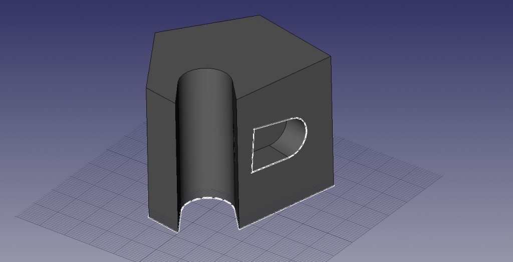
- Create a pocket from the second sketch, on the first object
Which gives you an object like this:

At any moment, you can select the original sketches and modify them, or change the extrusion parameters of the pad or pocket operations, which will update the final object.
Working with the Draft and Arch workbenches
The Draft Workbench and Arch Workbench behave a bit differently than the other workbenches above, although they follow the same rules, which are common to all of FreeCAD. In short, while the Sketcher and PartDesign are made primarily to design single pieces, Draft and Arch are made to ease your work when working with several, simpler objects.
The Draft Workbench offers you 2D tools somewhat similar to what you can find in traditional 2D CAD applications such as AutoCAD. However, 2D drafting being far away from the scope of FreeCAD, don't expect to find there the full array of tools that these dedicated applications offer. Most of the Draft tools work not only in a 2D plane but also in the full 3D space, and benefit from special helper systems such as Work planes and object snapping.
The Arch Workbench adds BIM tools to FreeCAD, allowing you to build architectural models with parametric objects. The Arch workbench relies extensively on other modules such as Draft and Sketcher. All the Draft tools are also present in the Arch workbench, and most Arch tools make use of the Draft helper systems.
A typical workflow with Arch and Draft workbenches might be:
- Draw a couple of lines with the Draft Line tool
- Select each line and press the Wall tool to build a wall on each of them
- Join the walls by selecting them and pressing the Arch Add tool
- Create a floor object, and move your walls in it from the Tree view
- Create a building object, and move your floor in it from the Tree view
- Create a window by clicking the Window tool, select a preset in its panel, then click on a face of a wall
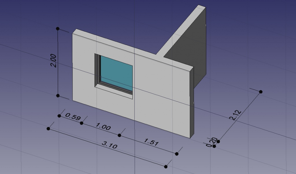
- Add dimensions by first setting the working plane if necessary, then using the Draft Dimension tool
Which will give you this:
More on the Tutorials page.
Scripting
And finally, one of the most powerful features of FreeCAD is the scripting environment. From the integrated python console (or from any other external Python script), you can gain access to almost any part of FreeCAD, create or modify geometry, modify the representation of those objects in the 3D scene or access and modify the FreeCAD interface. Python scripting can also be used in macros, which provide an easy method to create custom commands.
