Loslegen
Neuigkeiten
- Version 0.11 Release notes: Wichtiges zur Version 0.11 von FreeCAD
- Version 0.12 Release notes: Wichtiges zur Version 0.12 von FreeCAD
- Version 0.13 Release notes: Wichtiges zur Version 0.13 von FreeCAD
- Version 0.14 Release notes: Wichtiges zur Version 0.14 von FreeCAD
- Version 0.15 Release notes: Wichtiges zur Version 0.15 von FreeCAD
Vorwort
FreeCAD ist ein 3D CAD/CAE-Programm für parametrisches Modellieren. Es dient primär zum Entwerfen von technischen Objekten, kann aber auch zum Modellieren von anderen 3D Objekten genutzt werden, wo Präzision und Kontrolle über die Modellhistorie gefragt sind.
FreeCAD befindet sich in einem frühen Entwicklungsstadium und obwohl es Ihnen bereits eine lange (und stetig wachsende) Liste an Funktionen bereit stellt, fehlen verglichen mit kommerziellen Anwendungen noch viele Dinge. Es könnte also sein, dass FreeCAD nicht unbedingt den Entwicklungsstand für Herstellungsanwendungen erfüllt. Trotzdem gibt es eine schnell wachsende Gemeinschaft von enthusiastischen Anwendern, die sich im FreeCAD Forum austauschen. Wenn Sie neugierig sind, können sie einige hochwertige Beispiele erkunden, die mit Hilfe von FreeCAD erstellt wurden.
Wie alle Open-Source Projekte ist FreeCAD kein stringent entwickeltes Werk, das Ihnen auf dem Silbertablett serviert wird. Es hängt stark von der Gemeinschaft ab, ob es wächst, welche neue Funktionen implementiert werden und dass es auf allen (weit verbreiteten) Plattformen stabil läuft - neben dem gewöhnlichen Bugfixing. Also vergessen Sie bei der Benutzung von FreeCAD nicht: Es ist ein Gemeinschaftsprojekt, das durch alle weiter entwickelt wird und auch Sie können direkt dazu beitragen das Projekt FreeCAD voran zu treiben!
Installation
Laden Sie zuerst (falls noch nicht geschehen) FreeCAD bitte herunter und installieren Sie es. Auf der Download Seite finden Sie Informationen über aktuelle Versionen und Updates, auf der Installationsseite Informationen wie Sie FreeCAD installieren. Es gibt bereits Installationspakete für Windows (.msi), Ubuntu & Debian (.deb) openSUSE (.rpm) and Mac OSX. Da FreeCAD ein Open-Source Projekt ist, können ganz abenteuerliche Anwender den Quellcode betrachten und zusehen, wie brandneue Funktionen entwickelt werden.
FreeCAD erkunden
- Die 3D Ansicht zeigt den Inhalt der Datei
- Die Baumansicht zeigt die Hierarchie und Konstruktionshistorie aller Objekte in Ihrer Datei
- Die Objekteigenschaften zeigen die Eigenschaften aller selektierten Objekte an
- Das Ausgabefenster, in das FreeCAD Nachrichten, Warnungen und Fehlermeldungen ausgibt
- Die Python-Konsole, in der alle von FreeCAD ausgeführten Kommandos ausgegeben werden und wo Sie Python-Code direkt eingeben können
- Die Arbeitsbereichauswahl, mit der Sie den Arbeitsbereich wechseln können
The main concept behind the FreeCAD interface is that it is separated into workbenches. A workbench is a collection of tools suited for a specific task, such as working with meshes, or drawing 2D objects, or constrained sketches. You can switch the current workbench with the workbench selector (6). You can customize the tools included in each workbench, add tools from other workbenches or even self-created tools, that we call macros. There is also a generic workbench which gathers the most commonly used tools from other workbenches, called the complete workbench.
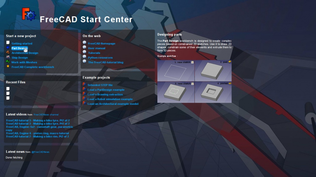
Wenn Sie FreeCAD das erste Mal starten, wird das Start Center geöffnet.

Das Start Center ermöglicht das schnelle Auswählen der gängigsten Arbeitsflächen, das Laden der zuletzt benutzten Dateien oder das Lesen der neuesten Nachrichten zu FreeCAD. Sie können die Standardarbeitsfläche in den Programmeinstellungen ändern.
FreeCAD bietet vier verschiedene Navigationsmodi, die sich durch die Art und Weise der Objektinteraktion in der Ansicht und der 3D-Ansicht unterscheiden. Einer dieser Modi ist speziell für Touchpads ausgelegt, bei dem die mittlere Maustaste nicht genutzt wird. Die nachstehende Tabelle beschreibt den standardmäßig eingestellten Modus CAD Navigation (Sie können den aktuellen Navigationsmodus über das Menü umschalten, das Sie durch einen Rechtsklick in einen leeren Bereich erhalten):
Es stehen mehrere Ansichtsvoreinstellungen (beispielsweise Draufsicht, Frontansicht, usw.) im Ansichtsmenü, auf der Ansichtssymbolleiste und über Tastenkürzel (1, 2, usw.) zur Verfügung. Mit einem Rechtsklick auf ein Objekt oder den Leerbereich der Ansicht steht ein schneller Zugriff auf allgemeine Vorgänge zur Verfügung, beispielsweise um eine bestimmte Ansicht oder ein Objekt in der Baumansicht auszuwählen.
Erste Schritte mit FreeCAD
Das Hauptaugenmerk von FreeCAD besteht darin, Ihnen zu ermöglichen, hochpräzise 3D Modelle zu erstellen, deren Eigenschaften Sie weiterhin genau kontrollieren und anpassen können (durch die Möglichkeit, in der Modellhistorie zurück zu gehen, und Parameter anpassen zu können) und gegebenenfalls auch die Fertigung dieser Modelle ( mittels 3D Druck, CNC Fräsen oder sogar bauarbeitsseitig). Es unterscheidet sich daher sehr von einigen anderen 3D Anwendungen, die für andere Einsatzzwecke wie z.B. Erstellen von Animationsfilmen oder Spielen programmiert wurden. Die Lernkurve von FreeCAD kann sehr steil sein, besonders wenn es Ihr erster Kontakt mit dem 3D Modellieren ist. Falls Sie an einigen Stellen nicht mehr weiter kommen, vergessen Sie nicht, dass es eine freundliche Community von Nutzern unter FreeCAD forum gibt, welche Ihnen schnell weiter helfen kann.
The workbench you will start using in FreeCAD depends on the type of job you need to do: If you are going to work on mechanical models, or more generally any small-scale objects, you'll probably want to try the PartDesign Workbench. If you will work in 2D, then switch to the Draft Workbench, or the Sketcher Workbench if you need constraints. If you want to do BIM, launch the Arch Workbench. If you are working with ship design, there is a special Ship Workbench for you. And if you come from the OpenSCAD world, try the OpenSCAD Workbench.
You can switch workbenches at any time, and also customize your favorite workbench to add tools from other workbenches.
Working with the PartDesign and Sketcher workbenches
The PartDesign Workbench is specially made to build complex objects, starting from simple shapes, and adding or removing pieces (that we call "features"), until you get to your final object. All the features you applied during the modelling process are stored in a separate view called the tree view, which also contains the other objects in your document. You can think of a PartDesign object as a succession of operations, each one applied to the result of the preceding one, forming one big chain. In the tree view, you see your final object, but you can expand it and retrieve all preceding states, and change any of their parameter, which automatically updates the final object.
The PartDesign workbench makes heavy use of another workbench, the Sketcher Workbench. The sketcher allows you to draw 2D shapes, which are defined by applying Constraints to the 2D shape. For example, you might draw a rectangle and set the size of a side by applying a length constraint to one of the sides. That side then cannot be resized anymore (unless the constraint is changed).
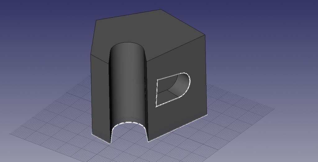
Those 2D shapes made with the sketcher are used a lot in the PartDesign workbench, for example to create 3D volumes, or to draw areas on the faces of your object that will then be hollowed from its main volume. This is a typical PartDesign workflow:
- Create a new sketch
- Draw a closed shape (make sure all points are joined)
- Close the sketch
- Expand the sketch into a 3D solid by using the pad tool
- Select one face of the solid
- Create a second sketch (this time it will be drawn on the selected face)
- Draw a closed shape
- Close the sketch
- Create a pocket from the second sketch, on the first object
Which gives you an object like this:

At any moment, you can select the original sketches and modify them, or change the extrusion parameters of the pad or pocket operations, which will update the final object.
Working with the Draft and Arch workbenches
The Draft Workbench and Arch Workbench behave a bit differently than the other workbenches above, although they follow the same rules, which are common to all of FreeCAD. In short, while the Sketcher and PartDesign are made primarily to design single pieces, Draft and Arch are made to ease your work when working with several, simpler objects.
The Draft Workbench offers you 2D tools a bit similar to what you can find in traditional 2D CAD applications such as AutoCAD. However, 2D drafting being far away from the scope of FreeCAD, don't expect to find there the full array of tools that these dedicated applications offer. Most of the Draft tools work not only in a 2D plane but also in the full 3D space, and benefit from special helper systems such as Work planes and object snapping.
The Arch Workbench adds BIM tools to FreeCAD, allowing you to build architectural models with parametric objects. The Arch workbench relies much on other modules such as Draft and Sketcher. All the Draft tools are also present in the Arch workbench, and most Arch tools make use of the Draft helper systems.
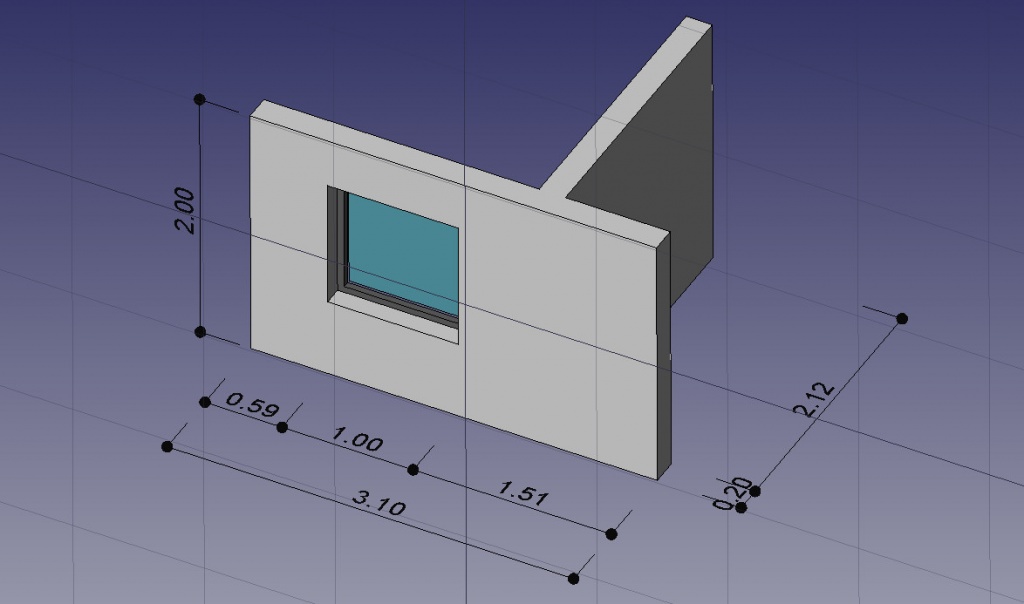
A typical workflow with Arch and Draft workbenches might be:
- Draw a couple of lines with the Draft Line tool
- Select each line and press the Wall tool to build a wall on each of them
- Join the walls by selecting them and pressing the Arch Add tool
- Create a floor object, and move your walls in it from the Tree view
- Create a building object, and move your floor in it from the Tree view
- Create a window by clicking the Window tool, select a preset in its panel, then click on a face of a wall
- Add dimensions by first setting the working plane if necessary, then using the Draft Dimension tool
Which will give you this:
Mehr Informationen finden sich auf der Anleitung Seite.
Scripting
Und zu guter Letzt, eine der mächtigsten Funktionen in FreeCAD ist die Skript-Umgebung. Über die integrierte Python-Konsole (oder durch jedes andere externe Python-Skript), können Sie auf nahezu jeden Teil von FreeCAD zugreifen, Geometrien erzeugen oder verändern, die Darstellung dieser Objekte in der 3D-Szene verändern oder auf die FreeCAD-Oberfläche zugreifen, bzw. diese verändern. Python-Skripting wird auch in Makros eingesetzt und stellt eine einfache Methode dar, eigene Skripte zu erstellen.


