Draft: Taglia/Estendi
|
|
| Posizione nel menu |
|---|
| Draft → Tronca/Estendi |
| Ambiente |
| Draft, Architettura |
| Avvio veloce |
| T R |
| Introdotto nella versione |
| - |
| Vedere anche |
| Parte → Estrudi |
Descrizione
Lo strumento Tronca/Estendi taglia o estende le Linee e le Polilinee in modo che finiscano in un'intersezione con un'altra linea o bordo.
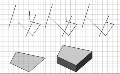
Segmento del contorno esteso, poi segmento tagliato; faccia estrusa in un corpo solido
Trim or extend
Usage
Options
The single character keyboard shortcut and the modifier keys mentioned here can be changed. See Draft Preferences.
- The solution with the largest length determines the default direction of the command. Hold down Alt to invert this direction.
- Hold down Shift to restrict the operation to the current segment of a Draft Wire.
- Press S to switch Draft snapping on or off.
Here is an example to explain the modifier keys. The left edge or the bottom edge of the U-shaped wire was extended. All Draft Snaps were turned off.
- Premere il tasto X, Y o Z per vincolare il punto sull'asse dato.
- Tenere premuto Maiusc per limitare l'operazione al segmento corrente ed evitare di prenderne un altro.
- Nel caso della modalità estrusione, Tenere premuto Maiusc per estrudere una faccia in una direzione che non è la normale.
- Tenere premuto Alt durante il taglio per invertire la direzione dell'operazione, cioè per tagliare l'altra estremità del contorno.
Extrude
Usage
See also: Draft Snap and Draft Constrain.
- It can be helpful to first change the Draft working plane so that it is not coplanar with the face you want to extrude.
- Optionally select a single face or an object with a single face.
- There are several ways to invoke the command:
- Press the
Draft Trimex button.
- Select the Modification →
Trimex option from the menu.
- Use the keyboard shortcut: T then R.
- Press the
- If you have not yet selected an object or a face: select an object with a single face in the 3D view.
- The Trimex task panel opens. See Options for more information.
- To define the extrusion direction and distance do one of the following:
Options
The modifier key mentioned here can be changed. See Draft Preferences.
- Hold Shift to extrude in a direction that is not parallel to the normal of the face.
Preferences
See also: Preferences Editor and Draft Preferences.
- To change the number of decimals used for the input of the distance: Edit → Preferences... → General → Units → Units settings → Number of decimals.
Scripting
Script
Vedere anche: Draft API e Nozioni di base sugli script di FreeCAD.
Non ci sono opzioni per questo strumento. Per l'estrusione di facce e altre forme consultare lo strumento Estrudi del modulo Parte.
extrusion = extrude(obj, vector, solid=False)
objis the object to be extruded.vectoris the extrusion direction and distance.- If
solidisTruea solid is created instead of a shell. extrusionis returned with the created object.
Example:
import FreeCAD as App
import Draft

doc = App.newDocument()

rectangle = Draft.make_rectangle(1500, 500)
doc.recompute()

vector = App.Vector(0, 0, 300)
solid = Draft.extrude(rectangle, vector, solid=True)
doc.recompute()
- Drafting: Line, Polyline, Fillet, Arc, Arc by 3 points, Circle, Ellipse, Rectangle, Polygon, B-spline, Cubic Bézier curve, Bézier curve, Point, Facebinder, ShapeString, Hatch
- Annotation: Text, Dimension, Label, Annotation styles, Annotation scale
- Modification: Move, Rotate, Scale, Mirror, Offset, Trimex, Stretch, Clone, Array, Polar array, Circular array, Path array, Path link array, Point array, Point link array, Edit, Subelement highlight, Join, Split, Upgrade, Downgrade, Wire to B-spline, Draft to sketch, Set slope, Flip dimension, Shape 2D view
- Draft Tray: Select plane, Set style, Toggle construction mode, AutoGroup
- Snapping: Snap lock, Snap endpoint, Snap midpoint, Snap center, Snap angle, Snap intersection, Snap perpendicular, Snap extension, Snap parallel, Snap special, Snap near, Snap ortho, Snap grid, Snap working plane, Snap dimensions, Toggle grid
- Miscellaneous: Apply current style, Layer, Manage layers, Add a new named group, Move to group, Select group, Add to construction group, Toggle normal/wireframe display, Create working plane proxy, Heal, Show snap toolbar
- Additional: Constraining, Pattern, Preferences, Import Export Preferences, DXF/DWG, SVG, OCA, DAT
- Context menu:
- Layer container: Merge layer duplicates, Add new layer
- Layer: Activate this layer, Select layer contents
- Text: Open hyperlinks
- Wire: Flatten
- Working plane proxy: Write camera position, Write objects state
- Getting started
- Installation: Download, Windows, Linux, Mac, Additional components, Docker, AppImage, Ubuntu Snap
- Basics: About FreeCAD, Interface, Mouse navigation, Selection methods, Object name, Preferences, Workbenches, Document structure, Properties, Help FreeCAD, Donate
- Help: Tutorials, Video tutorials
- Workbenches: Std Base, Arch, Assembly, CAM, Draft, FEM, Inspection, Mesh, OpenSCAD, Part, PartDesign, Points, Reverse Engineering, Robot, Sketcher, Spreadsheet, Start, Surface, TechDraw, Test Framework, Web
- Hubs: User hub, Power users hub, Developer hub

