Draft Bogen 3Punkte
|
|
| Menüeintrag |
|---|
| Entwurf → Bogenwerkzeuge → Bogen aus 3 Punkten |
| Arbeitsbereich |
| Draft, Arch |
| Standardtastenkürzel |
| A T |
| Eingeführt in Version |
| 0.19 |
| Siehe auch |
| Draft Bogen, Draft Kreis |
Beschreibung
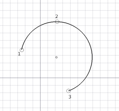
Das Werkzeug Draft Bogen 3Punkte erstellt einen Kreisbogen auf der aktuellen Arbeitsebene durch Eingabe von drei Punkten, die auf dem Umfang liegen; aus diesen drei Punkten werden Mittelpunkt und Radius bestimmt.
Ein Draft-Bogen ist eigentlich ein Draft-Kreis mit einer Daten-EigenschaftFirst Angle die nicht identisch ist mir der Daten-EigenschaftLast Angle.
Ein durch drei auf dem Umfang liegende Punkte festgelegter Bogen
Anwendung
See also: Draft Tray, Draft Snap and Draft Constrain.
- Drücke die Taste
Draft Arc 3Points Taste, oder drücke A dann T Tasten.
- Klicke auf einen ersten Punkt in der 3D-Ansicht, oder gib eine Koordinate and press the
Punkt hinzufügen Taste.
- Klicke auf einen zweiten Punkt in der 3D-Ansicht, oder gib eine Koordinate und drücke die
Punkt hinzufügen Taste.
- Klicke auf einen dritten Punkt in der 3D-Ansicht, oder gib eine Koordinate und drücke die
Punkt hinzufügen Taste.
- Der Bogen wird erstellt, nachdem der dritte Punkt angegeben wurde.
Optionen
The single character keyboard shortcuts available in the task panel can be changed. See Draft Preferences. The shortcuts mentioned here are the default shortcuts.
- To manually enter coordinates enter the X, Y and Z component, and press Enter after each. Or you can press the
Enter point button when you have the desired values. It is advisable to move the pointer out of the 3D view before entering coordinates.
- Press R or click the Relative checkbox to toggle relative mode. If relative mode is on, coordinates are relative to the last point, if available, else they are relative to the coordinate system origin.
- Press G or click the Global checkbox to toggle global mode. If global mode is on, coordinates are relative to the global coordinate system, else they are relative to the working plane coordinate system. introduced in version 0.20
- Press T or click the Continue checkbox to toggle continue mode. If continue mode is on, the command will restart after finishing, allowing you to continue creating arcs. introduced in version 0.20
- Press S to switch Draft snapping on or off.
- Press Esc or the Close button to abort the command.
Hinweise
- A Draft Arc can be edited with the Draft Edit command.
Einstellungen
Siehe auch: Voreinstellungseditor und Draft Einstellungen.
- To change the number of decimals used for the input of coordinates: Edit → Preferences... → General → Units → Units settings → Number of decimals.
- If the Edit → Preferences... → Draft → General settings → Draft tools options → Use Part Primitives when available option is checked, the command will create a non-editable Part Feature instead of a Draft Circle.
Eigenschaften
Siehe Draft Kreis.
Skripten
Siehe auch: Autogenerierte API Dokumentation und FreeCAD Grundlagen Skripten.
Zum Erstellen eines Draft-Bogens durch 3 Punkte wird die Methode make_arc_3points des Draft-Moduls verwendet:
arc = make_arc_3points(points, placement=None, face=False, support=None, map_mode="Deactivated", primitive=False)
- Creates an
arcobject from the givenpointslist. - If a
placementis given, the center of the circular arc will be moved to this place. See Placement for more information. - If
faceisTrue, the arc will make a face, that is, it will appear filled. - If
supportis given, it is aLinkSubList, that is, a list indicating an object and a subelement of that object. This is used so that the object appears referenced to this support.
- For example:
support=[(obj, ("Face1"))].
- If
map_modeis given, it is a string defining a type of mapping, for example:map_mode='FlatFace',map_mode='ThreePointsPlane', etc. See Part EditAttachment for more information. - If
primitiveisTrue, the arc created will be a simple Part Feature, not a complex Draft object.
Beispiel:
import FreeCAD as App
import Draft

doc = App.newDocument()

points = [App.Vector(0, 0, 0),
          App.Vector(5, 10, 0),
          App.Vector(10, 0, 0)]

arc = Draft.make_arc_3points(points)

doc.recompute()
- Drafting: Line, Polyline, Fillet, Arc, Arc by 3 points, Circle, Ellipse, Rectangle, Polygon, B-spline, Cubic Bézier curve, Bézier curve, Point, Facebinder, ShapeString, Hatch
- Annotation: Text, Dimension, Label, Annotation styles, Annotation scale
- Modification: Move, Rotate, Scale, Mirror, Offset, Trimex, Stretch, Clone, Array, Polar array, Circular array, Path array, Path link array, Point array, Point link array, Edit, Subelement highlight, Join, Split, Upgrade, Downgrade, Wire to B-spline, Draft to sketch, Set slope, Flip dimension, Shape 2D view
- Draft Tray: Select plane, Set style, Toggle construction mode, AutoGroup
- Snapping: Snap lock, Snap endpoint, Snap midpoint, Snap center, Snap angle, Snap intersection, Snap perpendicular, Snap extension, Snap parallel, Snap special, Snap near, Snap ortho, Snap grid, Snap working plane, Snap dimensions, Toggle grid
- Miscellaneous: Apply current style, Layer, Manage layers, Add a new named group, Move to group, Select group, Add to construction group, Toggle normal/wireframe display, Create working plane proxy, Heal, Show snap toolbar
- Additional: Constraining, Pattern, Preferences, Import Export Preferences, DXF/DWG, SVG, OCA, DAT
- Context menu:
- Layer container: Merge layer duplicates, Add new layer
- Layer: Activate this layer, Select layer contents
- Text: Open hyperlinks
- Wire: Flatten
- Working plane proxy: Write camera position, Write objects state
- Erste Schritte
- Installation: Herunterladen, Windows, Linux, Mac, Zusätzlicher Komponenten, Docker, AppImage, Ubuntu Snap
- Grundlagen: Über FreeCAD, Graphische Oberfläche, Mausbedienung, Auswahlmethoden, Objektname, Programmeinstellungen, Arbeitsbereiche, Dokumentstruktur, Objekteigenschaften, Hilf FreeCAD, Spende
- Hilfe: Tutorien, Video Tutorien
- Arbeitsbereiche: Std Base, Arch, Assembly, CAM, Draft, FEM, Inspection, Mesh, OpenSCAD, Part, PartDesign, Points, Reverse Engineering, Robot, Sketcher, Spreadsheet, Start, Surface, TechDraw, Test Framework, Web
