CAM Walkthrough for the Impatient: Difference between revisions
Renatorivo (talk | contribs) |
Renatorivo (talk | contribs) |
||
| Line 84: | Line 84: | ||
Finally we want to postprocess the paths and export the G-Codes to a file which we can upload to our CNC machine. |
Finally we want to postprocess the paths and export the G-Codes to a file which we can upload to our CNC machine. |
||
* We select the Job object in the tree |
* We select the Job object in the tree |
||
* We use the Path Postprocessing [[Image: |
* We use the Path Postprocessing [[Image:Path_PostProcess.png|32px]] tool to export the file. Before the file is written we can inspect it once more. |
||
[[File:Path-PostOutput.gif]] |
[[File:Path-PostOutput.gif]] |
||
Revision as of 18:19, 12 January 2018
Here we will show how to get from a simple FreeCAD object to the machine's G-Code
The model
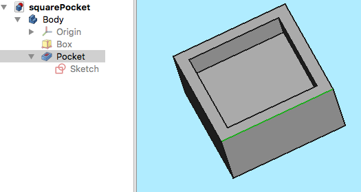
Let's start with a simple FreeCAD model: a cube with a rectangular pocket.
It is modeled straightforward in the Part Design using a Body, a Box and a Pocket based on a Sketch. The sketch is oriented in the XY plane.
The Tooltable
When we want to mill something we need a tool. The Tooltable is a collection of such tools.
The Job
In the Path workbench we create a ![]() Job
Job
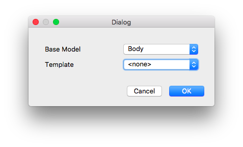
In the job creation dialog we select the Body as the Base Model and confirm with OK.
Job Output
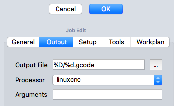
The model in the 3D view is now surrounded by a wireframe cube and the job configuration dialog opens. We start with the configuration of the output, which determines the finally generated G-Code file.
We can select a filename or we can use some placeholders, which we do here to create the output file in the same directory as the file with the square pocket. The filename will be the same as the FreeCAD model's name with the extension .gcode. Move the mouse over the input field to see further possibilities of placeholders.
Select the postprocessor which will translate the internal format into the code used by your machine. In the example we use the linuxcnc postprocessor.
The postprocessor can be configured with additional arguments which are shown as you move the mouse over the field. We use none of them here.
Job Setup
In the Setup subdialog we configure the stock. The model we have created in FreeCAD is what we want to have in the end. The stock is the material we start with. Here we use a cubic block of which we can configure the size here.
Job Tools
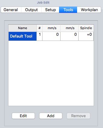
In the Tools section we add the previously defined tool. Don't forget in the tooltable to click the "Create Tool Controller" button. If you are not yet sure which tools to use, you can create the tool controllers later.
File:Path-ToolCreateController.png
We can delete the default tool and confirm the complete job configuration. The Workplan will be added later when we define the path operations.
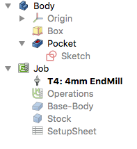
The tree should now look like this if we unfold the Job:
The Tool Controller
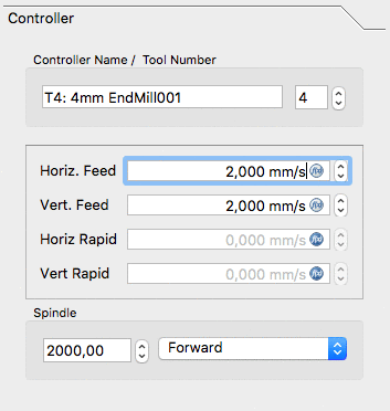
We have already created a tool controller during job creation. Now we want to define feed and speed for the usage of the tool in this job With a double click on the tool controller we enter the tool configuration. We have to enter the values for the feed rates in mm/s, which are FreeCAD's internally used units. The postprocessor has to transform these values into the correct units used by our machine.
We enter horizontal and vertical feedrates of 2mm/s and a spindle speed of 2000 rpm.
The Path Operations
We will add two operations for paths. The Contour operation will create a path around the box and the Pocket operation will create a path for the inner pocket.
For now we will keep it simple. We use the ![]() Contour button to open the Contour panel and confirm with OK without changing any of the values. We can see the green path around the object.
Contour button to open the Contour panel and confirm with OK without changing any of the values. We can see the green path around the object.
We select the bottom of the pocket and use the ![]() Pocket button to open the Pocket panel.
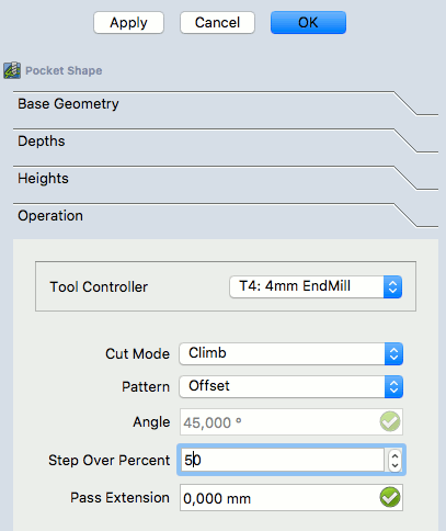
We leave Base Geometry, Depths and Heights as is and open the Operation subpanel
Pocket button to open the Pocket panel.
We leave Base Geometry, Depths and Heights as is and open the Operation subpanel
We change the pattern to "Offset" and "Step Over Percent" to 50 and confirm the pocket configuration with OK.
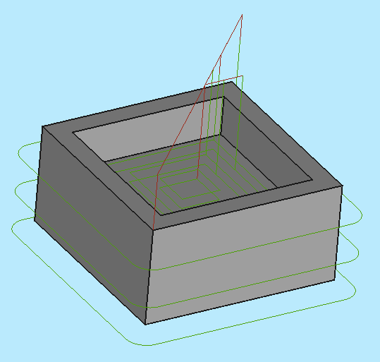
The result is a model with two paths:
Verifying Paths
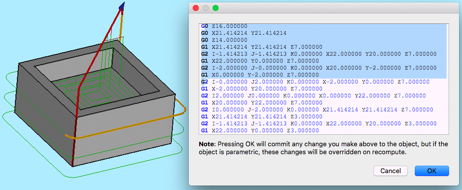
There are two ways to verify the paths created. We can inspect the G-Code and highlight the corresponding path segments or we can simulate the milling process.
To inspect the G-Code we use the ![]() tool. To highlight segments of the path we have to select the corresponding lines in the G-Code window.
tool. To highlight segments of the path we have to select the corresponding lines in the G-Code window.
To start the simulation we use the ![]() Path Simulator tool.
Path Simulator tool.
Export G-Code
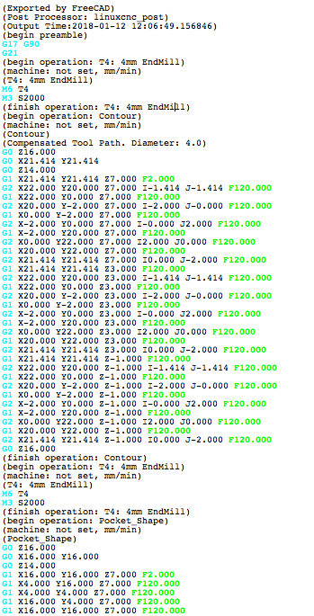
Finally we want to postprocess the paths and export the G-Codes to a file which we can upload to our CNC machine.
- We select the Job object in the tree
- We use the Path Postprocessing
 tool to export the file. Before the file is written we can inspect it once more.
Depending on the postprocessor used there might be additional parameters which can be set in the Job's configuration to show or suppress the intermediate steps.
