CAM Vcarve/it: Difference between revisions
m (FuzzyBot moved page Path Vcarve/it to CAM Vcarve/it without leaving a redirect: Part of translatable page "Path Vcarve") |
(Updating to match new version of source page) |
||
| Line 2: | Line 2: | ||
{{Docnav |
{{Docnav |
||
|[[ |
|[[CAM_Deburr|Deburr]] |
||
|[[ |
|[[CAM_Pocket_3D|Pocket 3D]] |
||
|[[ |
|[[CAM_Workbench|CAM]] |
||
|IconL= |
|IconL=CAM_Deburr.svg |
||
|IconR= |
|IconR=CAM_Pocket_3D.svg |
||
|IconC= |
|IconC=Workbench_CAM.svg |
||
}} |
}} |
||
{{GuiCommand |
{{GuiCommand |
||
|Name= |
|Name=CAM Vcarve |
||
|MenuLocation= |
|MenuLocation=CAM → Vcarve |
||
|Workbenches=[[ |
|Workbenches=[[CAM_Workbench|CAM]] |
||
|Version=0.19 |
|Version=0.19 |
||
}} |
}} |
||
| Line 19: | Line 19: | ||
==Description== |
==Description== |
||
The [[Image: |
The [[Image:CAM_Vcarve.svg|24px]] [[CAM_Vcarve|Vcarve]] tool is primarily for center-line engraving a [[Image:Draft_ShapeString.svg|24px|link=Draft_ShapeString]] [[Draft_ShapeString|Draft ShapeString]] onto a part. However, it may be useful for other kinds of 2D. |
||
Unlike engraving which follows the lines in the shapestring, V-carving uses a V-shaped cutter and attempts to clear the area by moving the cutter down the center of the region and varying the depth of cut. Since a v-cutter radius varies with the depth, the width of cut varies as well. The result is a more natural looking cut, particularly for serif fonts. |
Unlike engraving which follows the lines in the shapestring, V-carving uses a V-shaped cutter and attempts to clear the area by moving the cutter down the center of the region and varying the depth of cut. Since a v-cutter radius varies with the depth, the width of cut varies as well. The result is a more natural looking cut, particularly for serif fonts. |
||
| Line 36: | Line 36: | ||
* {{Button|[[File:Draft_ShapeString.svg|24px]] [[Draft_ShapeString|Draft ShapeStrings]]}} are usable out of the box |
* {{Button|[[File:Draft_ShapeString.svg|24px]] [[Draft_ShapeString|Draft ShapeStrings]]}} are usable out of the box |
||
* SVG files require some massaging, both in the editor and in the [[File:Workbench_Draft.svg|24px|link=Draft_Workbench]] [[Draft_Workbench|Draft Workbench]]: |
* SVG files require some massaging, both in the editor and in the [[File:Workbench_Draft.svg|24px|link=Draft_Workbench]] [[Draft_Workbench|Draft Workbench]]: |
||
** In the editor (e.g. [https://www.inkscape.org Inkscape]): make sure the file only contains paths and that the paths are ungrouped; make sure there are no self-intersecting paths, (in Inkscape) use |
** In the editor (e.g. [https://www.inkscape.org Inkscape]): make sure the file only contains paths and that the paths are ungrouped; make sure there are no self-intersecting paths, (in Inkscape) use CAM → Simplify and union to join paths that overlap. |
||
** Switch to the [[File:Workbench_Draft.svg|24px|link=Draft_Workbench]] [[Draft_Workbench|Draft Workbench]] in [[Std_Workbench|workbench dropdown list]] |
** Switch to the [[File:Workbench_Draft.svg|24px|link=Draft_Workbench]] [[Draft_Workbench|Draft Workbench]] in [[Std_Workbench|workbench dropdown list]] |
||
** Import the SVG using {{MenuCommand|File → Import → select "SVG as geometry"}} |
** Import the SVG using {{MenuCommand|File → Import → select "SVG as geometry"}} |
||
| Line 43: | Line 43: | ||
**:{{Caption|Above: Results of importing 'SVG as geometry'}} |
**:{{Caption|Above: Results of importing 'SVG as geometry'}} |
||
:::Paths with holes (letters, the vine in the image above) are imported as 2 separate paths (named along the lines of {{incode|Path905}} and {{incode|Path905001}} in the [[Tree_view|Tree view]]), one of them is the hole and the other one is the outline; we'll deal with this in the next step |
:::Paths with holes (letters, the vine in the image above) are imported as 2 separate paths (named along the lines of {{incode|Path905}} and {{incode|Path905001}} in the [[Tree_view|Tree view]]), one of them is the hole and the other one is the outline; we'll deal with this in the next step |
||
** In order to get the 2D faces, [[ |
** In order to get the 2D faces, [[CAM_Vcarve|CAM Vcarve]] needs: |
||
*** For paths <u>without</u> holes: |
*** For paths <u>without</u> holes: |
||
***# Select the path |
***# Select the path |
||
| Line 57: | Line 57: | ||
=== Create the Vcarve operation === |
=== Create the Vcarve operation === |
||
* Switch to the {{Button|[[File: |
* Switch to the {{Button|[[File:Workbench_CAM.svg|16px]] [[CAM_Workbench|CAM Workbench]]}} in the [[Std_Workbench|workbench dropdown menu]] |
||
* Add a job, use the objects named {{incode|Face<number>}} (or the ShapeString) as a base, add a v-bit tool controller, set feeds, speeds, etc. |
* Add a job, use the objects named {{incode|Face<number>}} (or the ShapeString) as a base, add a v-bit tool controller, set feeds, speeds, etc. |
||
* The operation only supports one object (either a single Face object, or a ShapeString) so for each object: |
* The operation only supports one object (either a single Face object, or a ShapeString) so for each object: |
||
** Select {{MenuCommand| |
** Select {{MenuCommand|CAM → [[Image:CAM_Vcarve.svg|24px]] Vcarve}} from the top menu. This opens the configuration panel. |
||
** Open the {{KEY|Base Geometry}} tab and add all faces of the ShapeString, or the face of a single Face object obtained above |
** Open the {{KEY|Base Geometry}} tab and add all faces of the ShapeString, or the face of a single Face object obtained above |
||
** Press {{Button|Apply}} and inspect the generated path; if necessary, adjust operation parameters (Threshold can be set higher in most situations) |
** Press {{Button|Apply}} and inspect the generated path; if necessary, adjust operation parameters (Threshold can be set higher in most situations) |
||
| Line 130: | Line 130: | ||
{{Docnav |
{{Docnav |
||
|[[ |
|[[CAM_Deburr|Deburr]] |
||
|[[ |
|[[CAM_Pocket_3D|Pocket 3D]] |
||
|[[ |
|[[CAM_Workbench|CAM]] |
||
|IconL= |
|IconL=CAM_Deburr.svg |
||
|IconR= |
|IconR=CAM_Pocket_3D.svg |
||
|IconC= |
|IconC=Workbench_CAM.svg |
||
}} |
}} |
||
{{ |
{{CAM_Tools_navi{{#translation:}}}} |
||
{{Userdocnavi{{#translation:}}}} |
{{Userdocnavi{{#translation:}}}} |
||
Revision as of 14:32, 26 March 2024
|
|
| Menu location |
|---|
| CAM → Vcarve |
| Workbenches |
| CAM |
| Default shortcut |
| None |
| Introduced in version |
| 0.19 |
| See also |
| None |
Description
The Vcarve tool is primarily for center-line engraving a
Draft ShapeString onto a part. However, it may be useful for other kinds of 2D.
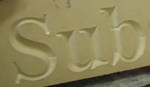
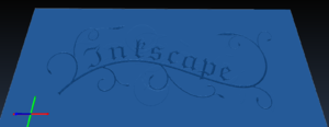
Unlike engraving which follows the lines in the shapestring, V-carving uses a V-shaped cutter and attempts to clear the area by moving the cutter down the center of the region and varying the depth of cut. Since a v-cutter radius varies with the depth, the width of cut varies as well. The result is a more natural looking cut, particularly for serif fonts.
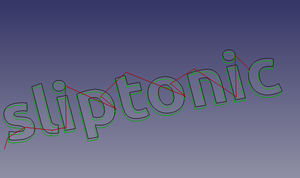
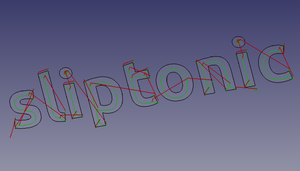
The V-carve algorithm calculates a path down the center-line of a region using a Voronoi diagram. This center-line is the path the tool will follow in the XY plane. It next calculates a 'maximum inscribed circle' along the path. This is the largest circle that can be drawn at that point and remain entirely inside the clearing area. Using the circle radius and the tip angle of the cutter, the depth of cut is calculated.
Usage
Prepare the shapes to engrave
Draft ShapeStrings are usable out of the box
- SVG files require some massaging, both in the editor and in the
Draft Workbench:
- In the editor (e.g. Inkscape): make sure the file only contains paths and that the paths are ungrouped; make sure there are no self-intersecting paths, (in Inkscape) use CAM → Simplify and union to join paths that overlap.
- Switch to the
Draft Workbench in workbench dropdown list
- Import the SVG using File → Import → select "SVG as geometry"
- The result should look similar to this:
- Paths with holes (letters, the vine in the image above) are imported as 2 separate paths (named along the lines of
Path905andPath905001in the Tree view), one of them is the hole and the other one is the outline; we'll deal with this in the next step
- Paths with holes (letters, the vine in the image above) are imported as 2 separate paths (named along the lines of
- In order to get the 2D faces, CAM Vcarve needs:
- For paths without holes:
- For paths with holes:
- Select the outer path, then the inner path
- Choose Modification →
Downgrade twice
- In order to get the 2D faces, CAM Vcarve needs:
Create the Vcarve operation
- Switch to the
CAM Workbench in the workbench dropdown menu
- Add a job, use the objects named
Face<number>(or the ShapeString) as a base, add a v-bit tool controller, set feeds, speeds, etc. - The operation only supports one object (either a single Face object, or a ShapeString) so for each object:
- Select CAM →
Vcarve from the top menu. This opens the configuration panel.
- Open the Base Geometry tab and add all faces of the ShapeString, or the face of a single Face object obtained above
- Press Apply and inspect the generated path; if necessary, adjust operation parameters (Threshold can be set higher in most situations)
- Press OK to finish
- Select CAM →
Options
Empty
Properties
Data
Base
- DatiPlacement: -
- DatiLabel: -
Depth
- DatiClearanceHeight: -
- DatiFinalDepth: -
- DatiSafeHeight: -
- DatiStartDepth: -
- DatiStepDown: -
Op Values
- DatiOpFinalDepth: -
- DatiOpStartDepth: -
- DatiOpStockZMax: -
- DatiOpStockZMin: -
- DatiOpToolDiameter: -
Path
- DatiActive: -
- DatiComment: -
- DatiCoolantMode: -
- DatiStartVertex: -
- DatiToolController: -
- DatiUserLabel: -
Hidden
- DatiBase: -
- DatiBaseObject: -
- DatiBaseShapes: -
- DatiExpressionEngine: -
- DatiLabel2: -
- DatiPath: -
- DatiProxy: -
- DatiVisibility: -
View
Empty
Scripting
See also: FreeCAD Scripting Basics.
Example:
#Place code example here.
- Project Commands: Job, Post Process, Check the CAM job for common errors, Export Template
- Tool Commands: Inspect CAM Commands, CAM Simulator, Finish Selecting Loop, Toggle the Active State of the Operation, ToolBit Library editor, ToolBit Dock
- Basic Operations: Profile, Pocket Shape, Drilling, Face, Helix, Adaptive, Slot, Engrave, Deburr, Vcarve
- 3D Operations: 3D Pocket, 3D Surface, Waterline
- CAM Modification: Copy the operation in the job, Array, Simple Copy
- Specialty Operations: Thread Milling
- Miscellaneous: Area, Area workplane
- ToolBit architecture: Tools, ToolShape, ToolBit, ToolBit Library, ToolController
- Additional: Preferences, Scripting
- Getting started
- Installation: Download, Windows, Linux, Mac, Additional components, Docker, AppImage, Ubuntu Snap
- Basics: About FreeCAD, Interface, Mouse navigation, Selection methods, Object name, Preferences, Workbenches, Document structure, Properties, Help FreeCAD, Donate
- Help: Tutorials, Video tutorials
- Workbenches: Std Base, Arch, Assembly, CAM, Draft, FEM, Inspection, Mesh, OpenSCAD, Part, PartDesign, Points, Reverse Engineering, Robot, Sketcher, Spreadsheet, Surface, TechDraw, Test Framework
- Hubs: User hub, Power users hub, Developer hub

