Architektura: Płaszczyzna przekroju
|
|
| Lokalizacja w menu |
|---|
| Architektura → Płaszczyzna przekroju |
| Środowisko pracy |
| Architektura |
| Domyślny skrót |
| S P |
| Wprowadzono w wersji |
| - |
| Zobacz także |
| Widok 2D kształtu, Wstaw obiekt środowiska Architektura |
Opis
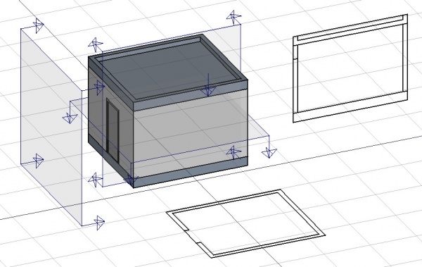
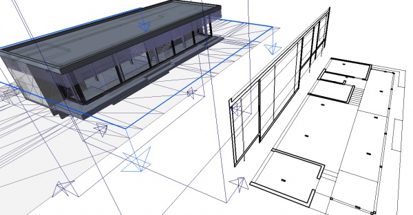
Narzędzie to umieszcza w bieżącym dokumencie płaszczyznę przekroju "rzecz", która definiuje przekrój lub płaszczyznę widoku. "Rzecz" przyjmuje swoje położenie zgodnie z bieżącą płaszczyzną przekroju i może być przenoszona i zmieniana jej orientacja poprzez przesuwanie i obracanie, aż opisze widok 2D, który chcesz uzyskać. Obiekt płaszczyzny przekroju uwzględnia tylko określony zestaw obiektów. Obiekty wybrane podczas tworzenia płaszczyzny przekroju zostaną automatycznie dodane do tego zestawu. Inne obiekty mogą być później dodawane lub usuwane z obiektu Płaszczyzny przekroju za pomocą narzędzi Połącz obiekty i Usuń komponent lub poprzez dwukrotne kliknięcie Płaszczyzny przekroju w widoku drzewa.
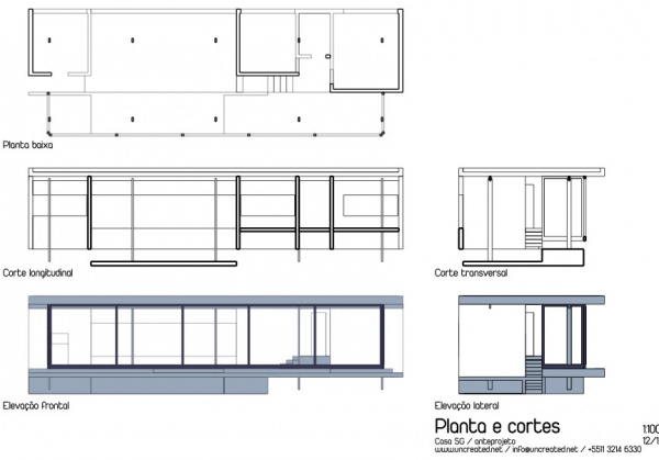
Sama Płaszczyzna przekroju nie utworzy żadnego widoku swojego zestawu obiektów. W tym celu należy utworzyć Widok architektury, aby utworzyć widok na stronie rysunku technicznego.
Użycie
- Opcjonalnie ustaw płaszczyzne roboczą, aby odzwierciedlała płaszczyznę, na której chcesz umieścić płaszczyznę przekroju.
- Wybierz obiekty, które chcesz uwzględnić w widoku przekroju.
- Naciśnij przycisk
Płaszczyzna przekroju lub naciśnij S, a następnie P.
- Ustaw płaszczyznę przekroju we właściwej pozycji przesuwając / obracając, jeśli to konieczne.
- Wybierz płaszczyznę przekroju, jeśli nie została jeszcze wybrana.
- Użyj narzędzia Widok 2D kształtu lub Wstaw obiekt środowiska Architektura, aby utworzyć widok.
Opcje
- The Section plane object will only consider a certain set of objects, not all the objects of the document. Objects can be added or removed from a SectionPlane object by using the Arch Add and Arch Remove tools, or by double-clicking the Section Plane in the tree view, selecting objects either in the list of in the 3D scene, and pressing the add or remove buttons.
- With a section plane object selected, use the Draft Shape2DView tool to create a shape object representing the section view in the document.
- Create TechDraw ArchView.
- The Section Plane can also be used to show the entire 3D view cut by an infinite plane. This is only visual, and won't affect the geometry of the objects being cut.
Properties
- DANEOnly Solids: If this is True, non-solid objects in the set will be disregarded
- WIDOKDisplay Length: The length of the section plane gizmo in the 3D view. Doesn't affect the resulting view
- WIDOKDisplay Height: The height of the section plane gizmo in the 3D view. Doesn't affect the resulting view
- WIDOKArrow Size: The size of the arrows of the section plane gizmo in the 3D view. Doesn't affect the resulting view
- WIDOKCut View: If this is
true, the whole 3D view will be cut at the location of this section plane. - WIDOKClip view: if this is
true, it will clip the view to the display height and length of the section plane. This effectively turns the section plane into an orthographic camera, limiting the field of view.
The Arch SectionPlane with the clip view option will behave like a camera, limiting the field of view.
Tweaks
- Adding manually a property named RotateSolidRender of type App::PropertyAngle to the section plane's View properties (right-click the properties view -> show all, right-click again -> add property) allows to rotate the render when using Solid mode. This is useful when a rendered view has for example both Arch and Draft elements, and the rendering of the Arch elements is rotated in relation to the Draft elements.
Tworzenie skryptów
Zobacz również: API: Architektura i Podstawy tworzenia skryptów FreeCAD.
Narzędzie Płaszczyzna przekroju może być używane w makrodefinicjach i z konsoli Python za pomocą następujących funkcji:
Section = makeSectionPlane(objectslist=None, name="Section")
- Tworzy obiekt
Sectionzobjectslist, który jest listą obiektów.
Przykład:
import FreeCAD, Draft, Arch

p1 = FreeCAD.Vector(0, 0, 0)
p2 = FreeCAD.Vector(2000, 0, 0)
baseline = Draft.makeLine(p1, p2)
baseline2 = Draft.makeLine(p1, -1*p2)

Wall1 = Arch.makeWall(baseline, length=None, width=150, height=2000)
Wall2 = Arch.makeWall(baseline2, length=None, width=150, height=1800)
Structure = Arch.makeStructure(length=1000, width=1000, height=200)
FreeCAD.ActiveDocument.recompute()

BuildingPart = Arch.makeBuildingPart([Wall1, Wall2])

Floor = Arch.makeFloor([BuildingPart])
Building = Arch.makeBuilding([Floor, Structure])
Site = Arch.makeSite(Building)
FreeCAD.ActiveDocument.recompute()

Section1 = Arch.makeSectionPlane([Wall1, Wall2])
Section2 = Arch.makeSectionPlane([Structure])
Section3 = Arch.makeSectionPlane([Site])
FreeCAD.ActiveDocument.recompute()
- Elementy: Mury, Konstrukcja, ściana kurtynowa, Okna, Drzwi, Dach, Kubatura, Schody, Wyposażenie, Ramy, Ogrodzenie, Kratownica, Profil, Rura, Kształtka
- Zbrojenie: Pręty zbrojeniowe proste, Pręty zbrojeniowe typu U, Pręty zbrojeniowe typu L, Strzemiona, Strzemiona, Pręty zbrojeniowe spiralne, Zbrojenie słupów, Zbrojenie belek, Zbrojenie płyt stropowych, Zbrojenie stóp fundamentowych, Pręt zbrojeniowy
- Panels: Panel, Panelizacja do cięcia, Arkusz panela, Zagnieżdżanie
- Materiał: Wybór materiału, Materiał złożony
- Organizacja: Część budowli, Projekt, Teren, Budowla, Piętro, Odniesienie, Płaszczyzna przekroju, Obmiar
- Osie: Osie, Układ osi, Siatka
- Modifikacja: Płaszczyzna cięcia, Komponent dodaj, Komponent usuń, Przegląd
- Narzędzia: Komponent, Klonuj komponent, Podziel siatkę, Siatka na kształt, Zaznacz siatki nie bryłowe, Usuń kształt., Zamknij otwory, Połącz ściany, Sprawdź, Przełącz flagę Brep IFC, Trzy widoki, Arkusz kalkulacyjny IFC, Przełącz widoczność odjęcia
- Dodatkowe: Preferencje, Ustawienia Importu i Eksportu (IFC, DAE, OBJ, JSON, 3DS); SHP), Architektura: API
- Jak zacząć
- Instalacja: Pobieranie programu, Windows, Linux, Mac, Dodatkowych komponentów, Docker, AppImage, Ubuntu Snap
- Podstawy: Informacje na temat FreeCAD, Interfejs użytkownika, Profil nawigacji myszką, Metody wyboru, Nazwa obiektu, Edytor ustawień, Środowiska pracy, Struktura dokumentu, Właściwości, Pomóż w rozwoju FreeCAD, Dotacje
- Pomoc: Poradniki, Wideo poradniki
- Środowiska pracy: Strona Startowa, Architektura, Assembly, CAM, Rysunek Roboczy, MES, Inspekcja, Siatka, OpenSCAD, Część, Projekt Części, Punkty, Inżynieria Wsteczna, Robot, Szkicownik, Arkusz Kalkulacyjny, Powierzchnia 3D, Rysunek Techniczny, Test Framework


